***UPDATED! K12-G tube amp problem UPDATED!***
***Thread was merged please see the end if you could help. ***
Hello everyone,
I am new here but have referenced here many times for help and browse for the pure enjoyment.
I have the amp listed above and it is about 1 1/2 years old. I am having a problem that I would like some advice on.
Last night I turned the amp on for the first time in about a week. I noticed that the left channel was louder than the right. This has happened before and it was the volume pot. I removed the pot and tried the amp with no volume control...the problem still existed. I then removed the amp from the receiver and used the receiver to drive the speakers. Normally the amp powers the speakers and get it's input from the receiver's preamp output. Using the receiver only the problem went away. I then swapped the left and right channel tubes and the problem moved over to the right channel. Does this sound like a tube problem? What can I do to confirm?
I was frustrated and wanted to make sure I was hearing correctly so I used a low frequency bass track to better hear any differences between the channels. After a few minutes the left channel died. By the way I had switched the tubes back to their original configuration. What happened?
I went to bed and this morning, to my surprise, the was working again on both channels. However, the amp is distorting at a much lower volume than ever before. It isn't that powerful but normally it will drive the speakers more clearly up to a higher volume. Is this tube damage?
For what it is worth I performed most of the modifications here:
S5 Electronics K-12M Tube Amp
I also installed Hammond PT 1609 output transformers.
What do you'll think? Thank you very much.
John
Last edited:
Hi John - Welcome to the Forum
As the problem moved with the tubes looks like you have already confirmed it. Whether the problem has originated within the tube is another question. My worry would be the possibility of damage to your nice 1609's if you continue to run this amp as is.
Have you noticed any unusual red hot spots on the metal plates inside the tube?
I would want to know if the tubes weren't conducting excessive current.
Did you do the ccs mod and if so can it be easily exchanged for the original cathode resistor in order to rule out a faulty ccs?
I'm afraid I'm raising more potential problems than solutions here.....
Bill
I then swapped the left and right channel tubes and the problem moved over to the right channel. Does this sound like a tube problem? What can I do to confirm?
As the problem moved with the tubes looks like you have already confirmed it. Whether the problem has originated within the tube is another question. My worry would be the possibility of damage to your nice 1609's if you continue to run this amp as is.
Have you noticed any unusual red hot spots on the metal plates inside the tube?
I would want to know if the tubes weren't conducting excessive current.
Did you do the ccs mod and if so can it be easily exchanged for the original cathode resistor in order to rule out a faulty ccs?
I'm afraid I'm raising more potential problems than solutions here.....
Bill
Last edited:
Bill
I did not do the CCS modification and I have not noticed any hot spots on the tubes. How would I go about determining the current at the tubes or testing the tubes for that matter? Among my tools I do own a nice Fluke multimeter, but unfortunately no tube test or scope.
If new tubes are in order, would there be any gain to going with a different type or am I showing my ignorance of tube circuitry and their matched parts?
John
The fluke will do just fine for checking the bias voltages on the tubes.
I have the schematic somewhere and will get back to you when I've refreshed my memory.
Someone more knowledgable ( and there are many .... ) may chip in before that.
IIRC your tubes uses 10 or 11 volt heaters so you dont have a lot of choice here.
Incidently I built the K502 kit which is very similar to yours and I also have put in the 1609's - big improvement. It uses the 11bm8 tube.
I have the schematic somewhere and will get back to you when I've refreshed my memory.
Someone more knowledgable ( and there are many ....
) may chip in before that.IIRC your tubes uses 10 or 11 volt heaters so you dont have a lot of choice here.
Incidently I built the K502 kit which is very similar to yours and I also have put in the 1609's - big improvement. It uses the 11bm8 tube.
Hi John,
Looks like your amp uses the 10gv8 tube - is that correct?
If so then I'm probably looking at the right schematic - I would post it but I'm not sure if that would be in breach of copywright.
Looks like the two pushpull output pentode sections in each channel have their cathodes tied together with a single 150 ohm resistor ( R8 and R17 ). Measuring the voltage across this resistor will give us the current through it ( from Ohms' law ). Unfortunately this will only give us the total current supplied to both pentodes and not their individual current used. We will though be able to compare the current usage of one channel with the other and if it's around the expected value. Will need to look up the specs for your tube and get back to you. No music should be playing while these measurements are taken.
Bill
You are correct, they are 10gv8 tubes. I measure across R8(right) and get 16.86 Vdc and across R17(left) and get 16.96 Vdc.
The odd thing is that earlier this morning it was playing again, both channels that is, as opposed to one. The "power" doesn't seem to be there though. Poor bass response and distortion at what seems like a lower volume than I recall previously.
Thanks again, this is great.
John
http://www.diyaudio.com/forums/tubes-valves/153217-10gv8-bias-point-k-12g.html
Having read the above thread I'm persuaded the 10gv8's are being driven too hard. Perhaps (in the short term) investing in a set of new valves would cure your problem. If the problem still persists you can start to look elsewhere. In the longer term I would want to reduce the cathode current, perhaps with a ccs. I wonder how hard other K12G owners are driving their 10gv8's
Brgds Bill
The odd thing is that earlier this morning it was playing again, both channels that is, as opposed to one.
The amp has had chance to cool down overnight after the tough workout you gave it with the high energy low frequency bass track. May indicate a temperature dependent fault though.
Thank you for the thoughts, I might just be replacing some tubes.
So, if I understand correctly, at idle these tubes are at 112 mA on the right and 113 mA on the left? But this is through both correct?
Sounds like the threads regarding this tube indicate an ideal amperage of around 50mA? I wonder how others are driving theirs as well.
The CCS idea isn't something I'm familiar with, other than looking it up to answer your question about whether I had performed the modification.
John
So, if I understand correctly, at idle these tubes are at 112 mA on the right and 113 mA on the left?
That's what the maths tell me also......
But this is through both correct?
Yes, and even if we make the assumption of the current being shared equally between the pentode sections that still means around a 10% increase over the " ideal " 50mA.
Perhaps somebody more knowledgable could have another look at the 10gv8 load lines to see if 50 mA at 210vdc (my assumption of your B+) is indeed what you should be aiming for.
Constant Current Source (ccs) - In some amps the cathode resistance can be adjusted so that as the tube ages it can be kept within its operating range. A way of getting around this adjustment is to use a ccs. There are arguments for and against the use of a ccs in the output stage but IMHO they are convenient. Just to hear the difference a ccs would make I replaced my K502 cathode resistors ( also R8 and R18 ) with a simple ccs using the LM317 chip and a single resistor. The resistor is used to set the desired current level of the ccs. Here are some links.
YH's Lazy Man Constant Current Source
http://www.freewebs.com/valvewizard/ccs.html
Last edited:
Thanks Bill
The ccs idea looks easy enough...if I could find the room in the inclosure to place them. I really appreciate your thoughts on this. I am hoping that I can get a second opinion as well...maybe someone else has some thoughts?
I found the tubes from S5 electronics for around $30 but I hate to spend it if that isn't the problem. I don't know, I just don't have enough experience to know if that 10% is really a problem or not.
John
I just don't have enough experience to know if that 10% is really a problem or not.
Rightly or wrongly this is the way your amp has been designed. It seems to me that all K12G owners are in the same boat. ( Ahoy - anyone out there.....
 )
)It's always good to have spare tubes, even two would be enough to allow you to check out one channel then the other. If the problem lies elsewhere you'll know.
The ccs is something that can be experimented later once your happy you've got your amp back the way it was.
Brgds Bill
Bill
Thanks for all the help. The amp is on the bench right now waiting for a fix. I am tempted to buy a new set of tubes...if for nothing else, a backup set would be good.
Maybe I'll try that emoticon and it will bring in the troops...
...bump...
I love the amp but something is definitely not the same.
John
I love the amp but something is definitely not the same.
I love mine too , but since I pulled out the 1609's and built a Baby Huey with them things are definitely not the same either.......
More k12g amp musings
Much thanks to soonerorlater for all of the help with my recent questions.
I installed a standby switch which helps a lot with the popping when turning off the amp. After some cleaning the amp seems to be running fine, no more drastic differences between channels or dropping of the left channel.
However I am curious if there is a good way to check channel balance with a multimeter?? I am also possibly coming into an oscilloscope...would I be able to do the above test with it? I suspect it will come in handy for checking but I'm not at all familiar with them! Excited to learn! What do you'll think? Oscilloscope or not?
Thanks so much
John
So John, did you get it working with new tubes? Since the problem moved with the tubes it is definitely a tube issue. You should try moving only one tube at a time to figure out which one is your problem.
I just completed the same kit with the 10GV8 tubes. It sounds great. It seems that the tubes are being driven a bit hard though. They get REALLY hot.
I measured the current through them by measuring the voltage drop across the output transformer winding. I then turned off the amp and measured the resistance across the same winding. I calculated 47mA. I then measured the voltage across the tube (from cathode to plate) and got 192V. This calculates out to 9 watts! The tube is rated at 7 watts according to the data sheet. I get 15.2V across the cathode resistor for a total of about 50mA per tube.
As noted in the other thread referenced by Soonerorlater, it was suggested to raise the value of the cathode resistor to a higher value to get the plate dissipation to 7 watts. This would be 36mA at 192V across the tube.
I think I might try this as the idle current through my 10GV8s is too high. 9 watts.
Last edited:
I have a K12-G from ~2007, and it too appears to be biased well beyond max. plate dissipation. Below is link showing the idle voltages I measured. When I did the math, I found that my idle current is dissipating 9.3W in the plate.
idle voltages for k12-g amp
Most data sheets suggest a max. plate dissipation of 7W. (Some also show 7W AND 9W, what's that mean!?). I'm going to reduce the power to lengthen tube life.
I'm considering putting in a 5-W potentiometer for the cathode bias resistor, and a "switchable" volt meter & amp meter (via switches I could assign these 2 meters to a particular tube, so that I can easily compute plate-power, and use the potentiometer to adjust bias.)
Thoughts on this modification?
Thanks all!
> my idle current is dissipating 9.3W in the plate.
Less. I get like 8.1 Watts/plate.
Ik/pair is 93mA, but about 6mA is screen current. Vpk is not 200V but 186V.
The 7W/9W ratings are explained in footnotes, but context has been lost. What were these tubes sold for? You on your test bench? Or many thousands of TV sets, maybe checked for picture but not verified in every detail? They want you to aim for <7W. This leaves room for manufacturing slop (tolerances) and miss-fit in the field (230V lines in a 220V district). The careful designer will also check for <9W "worst case", which is hard to define. This all smells of large safety-factor. The V-sweep tube of a TV is not a real critical part of design, but should not fail enough to get a bad reputation. 7W-9W will not make a TV model notorious.
Note also that in sweep work dissipation is nominally low but small circuit losses can raise dissipation greatly. It is not unusual for same-frame tubes to be rated 3/4 or 2/3rd when sold for TV sweep than when sold for audio which is much more consistent and much easier to measure.
And what is the consequence of a 10GV8 failure? A 30-day dog-sled trip to replace a $999 tube? No, it is $5 at the super-store and may be even cheaper if you shop around. When I buy $5 shoes I don't complain if they don't last a month.
Attachments
Me Too
I had the same issue with my fully-modded K12-G. Same symptoms. Mine had been heat-cycled every 24 as I played it each evening. So just because it was an easy task, I re-flowed the solder on the tube socket connections. Even the ones that looked fine.
Totally fixed the problem. Seemed to sound better, but that is a completely qualitative assessment.
Anyhow, a set of tubes is $20, so why not grab some spares?
All
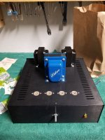
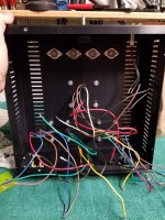
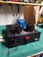
I am revisiting an amp that I once had working. It is a S5 K12G. Originally I had in it wooden enclosure and I had performed some modifications suggested on the various forums.
The last time I touched it was 6 years ago! I tore it down and then I got married, had a kid, etc. Anyway, at the time I had purchased some parts to change the enclosure and some key components. I recently pulled out the box of parts and started cutting/drilling the enclosure and mounting the components. I was sitting down and thinking about the wiring layout when it hit me. Did I buy the wrong PT 6 years ago?
The PT is an Edcor XPWR025-120. I am using a full bridge rectifier setup consisting of 4 UF4007s. Additionally I am using the Hammond 1609s in ultra linear. I know the tube heater voltage is 11.6 and the current is .45, so I believe that winding is correct. What am concerned about is the 200mA. The 180 volts seems ok.
Any help is very appreciated.
John
Attachments
- Status
- This old topic is closed. If you want to reopen this topic, contact a moderator using the "Report Post" button.
- Home
- Amplifiers
- Tubes / Valves
- K12G Questions