The easiest way to determine phase is to just power it up on completion and listen for a loud squeal. If you get it, then it's phased wrong because it's oscillating. Simply reverse the plate & screen connections on the output tubes, meaning one side to the other. Or reverse the coupling capacitors to the grids. So leave the transformer leads long till you're sure they're phased correctly.
Hammond said to connect the secondary windings together to get the most efficiency through better coupling. The lower 4 ohm winding could, in theory, be used as a tertiary winding for feedback. The advantage would be some isolation from the effects of speaker impedance variations. But I would go for the better coupling efficiency.
Going UL mode still keeps the screens connected and drawing some current so overall voltage level should be pretty much the same. If it increased at all it will only be a small around and well within acceptable tolerance.
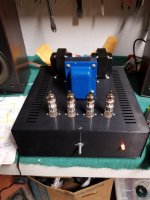
I like the chassis.
Hammond said to connect the secondary windings together to get the most efficiency through better coupling. The lower 4 ohm winding could, in theory, be used as a tertiary winding for feedback. The advantage would be some isolation from the effects of speaker impedance variations. But I would go for the better coupling efficiency.
Going UL mode still keeps the screens connected and drawing some current so overall voltage level should be pretty much the same. If it increased at all it will only be a small around and well within acceptable tolerance.
I like the chassis.
 @JTCamp - it’s against the Forum Rules to start multiple threads on the same topic, your threads have been merged.
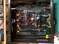
HollowState, thank you for your response. I'm trying to think about the layout as I go along but it's tough not to get stuck on all the little details. The chassis is pretty cool. I bought it from a vendor. It's anodized aluminum but it's modular; the panels go together with screws into captured nuts. Unfortunately there isn't electrical continuity between the panels... so i'm working on that too.
jazbo8, my apologies. I won't let it happen again.")
Thanks for all the help,
John
jazbo8, my apologies. I won't let it happen again.
Thanks for all the help,
John
All
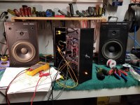
I completed the work last night and am happy that there is no hum what so ever. The sound is pretty good and there isn't any popping when I turn the power off. I remember the old setup doing this...I'm not sure what changed. However, I not excited about the temperature of the tubes and the PT.
My first question is about the tube temperature. Can someone explain to me how to determine if they are running too hot? I think this is called tube biasing and/or dissipation. I have a meter and am comfortable checking but I'm not sure how to do it. I have running plate and cathode voltages etc if that would help.
My second question is about the PT temperature. I'm going to try to get an amperage reading on the secondary B+ winding. I had been concerned that the 180 mA that the transformer is rated for wasn't enough. Once I get the reading, I'll post back.
Thanks for looking and please let me know what you think.
John
Attachments
Last edited:
Regarding the heat from the tubes... I found a calculator and did some adjustments. Calculator here Weber Bias Calculator
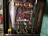
With the original 150 ohm common cathode resistors the calculator was saying 12W and 57 mA. That seems really high based on what I've read. I'm don't know what I doing though.
I found some resistor that in parallel give me 235 ohms of resistance. In the calculator it shows that to be 9 watts and 41 mA after making new voltage measurements. The tubes appear cooler but I'm pretty much in the dark on whether I'm going about this correctly.
Oh, and my hat is off to those who lay out a chassis with point to point wiring and make it look good and be functional. Really impressive.
Thanks,
John
All
I wanted to reply and apologize because this thread seems really confusing now that I've read it.
When this thread was merged recently I did not realize it was merged with a thread of mine from 8 years ago.
To that point, I created the most recent thread not remembering that I'd asked some similar questions the first time.
However, I still would like input if you can. Im concerned about the amperage on the secondary of the PT and the question of tube biasing for this amp.
Thank you
John
You seems to have two issues. One, the Edcor transformer you bought is under size for the K12G design. Second, you changed the output from Pentode to Ultra Linear without also correct the bias resistor. The good news is, the Edcor transformer should be able to support the push pull 10GV8 tubes if you pull back the power some.
I would increase the 235R output cathode (bias) resistor to limited the current to about 68mA per channel. Not having an UL 10GV8 curve to work with, my guess is, it should be around 320R or so. Use a volt meter and ohms law to find the right value. I = E/R
I would increase the 235R output cathode (bias) resistor to limited the current to about 68mA per channel. Not having an UL 10GV8 curve to work with, my guess is, it should be around 320R or so. Use a volt meter and ohms law to find the right value. I = E/R
Thanks for replying. I'm going to get a selection of resistors and test the amp with them.
Can you explain how changing to ultra linear requires a bias change? Is it because of the changing of the plate voltage?
Also my reading of .45 amps on the PT seems really high. In my reading about this amp design, I have found at the most 300 mA. Is there a way to calculate the theoretically amperage? I assuming there is because you mentioned 68 mA per channel. Could changing the capacitor values on the power supply section help to give the transformer more head room? I have 4 UF4007 diodes taking the place of the original diode bridge but otherwise this section is unchanged.
So with more reading, I've discovered that the rating on the transformer is typically based on half wave rectification. In this amp's case there is full wave rectification. To that point, the AC amperage rating needs to be about 1.6 times that of the DC amperage load. Several of you have said that this amp would use about 150 mA. So I would need at least 250 mA of current available for this amp in stock form. Sad Face. Any creative recommendations for making this PT work?
John
John,
Do you still have the stock PT? The reason I ask, is that you could use it to get the 170V@300ma you need to drive the audio circuit and then use a separate filament transformer to run the tube heaters. This would unload the PT heater winding and reduce the heat by about 30 percent, give or take. I am going to do this with a K amp build using the board and 6gv8 tubes. That PT does run on the ragged edge with respect to heat and I hope this scheme will create a more reliable situation.
Jamie
Jamie,
I keep missing notifications. Anyway, I don't have the original transformer but Edcor can wind me a custom XPWR025 with 350mA capacity. My intention is to unbox the amp and measure the current on the secondary of the PT. I'll post results of where am at before ordering the new PT.
Thanks
John
I keep missing notifications. Anyway, I don't have the original transformer but Edcor can wind me a custom XPWR025 with 350mA capacity. My intention is to unbox the amp and measure the current on the secondary of the PT. I'll post results of where am at before ordering the new PT.
Thanks
John
- Status
- This old topic is closed. If you want to reopen this topic, contact a moderator using the "Report Post" button.
- Home
- Amplifiers
- Tubes / Valves
- K12G Questions