Hi all,
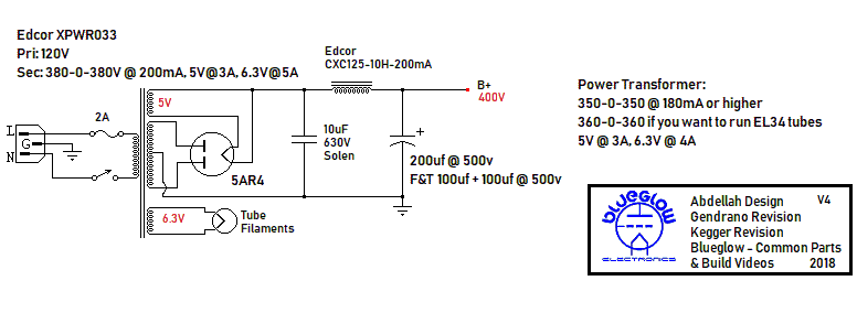
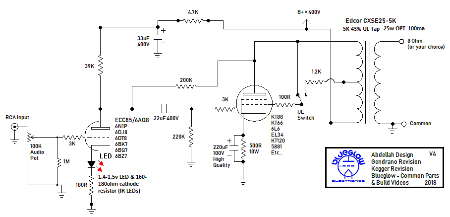
I was hoping to get some feedback on the layout for a KT88 single-ended amp that I'm building. I've built the S-5 K-12G in the past, and been wanting to build a simple single-ended amp for a while, and then I saw blueglow electronics was doing this exact build. Here's the schematics:
I'm basing my layout design on the Triode Labs 2A3 SET (2A3 SET Stereo — TRIODE LAB), with the power transformer and choke on one side, the output transformers on the other, the output tubes kinda in the center, and the driver tube to the far left.
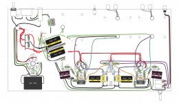
I've attached the internal wiring layout that I'm thinking about. On the layout, I just show the holes for the transformers/choke: the output transformers are on the right side of the image, the power transformer is on the left side, and the choke is next to the power transformer.
Does anybody see anything majorly wrong with the layour? This is my first time laying out an amp. I tried to keep the AC heater wires away from any signal wiring, and then I'm grounding everything back to a star ground (and then to chassis through an RC circuit).
A couple things I'm wondering about:
- Do the longer signal runs from the driver tube need to be shielded in some way?
- I have the ultra-linear/triode switch at the rear of the amp (I wanted it out of the way). Is that gonna be an issue with the longer runs to the switch and back?/
- I think the input wiring through the 100K pot could be cleaned up (just going direct to pot rather than through the terminal strips)
I'd love any suggestions! Thanks!
I was hoping to get some feedback on the layout for a KT88 single-ended amp that I'm building. I've built the S-5 K-12G in the past, and been wanting to build a simple single-ended amp for a while, and then I saw blueglow electronics was doing this exact build. Here's the schematics:
I'm basing my layout design on the Triode Labs 2A3 SET (2A3 SET Stereo — TRIODE LAB), with the power transformer and choke on one side, the output transformers on the other, the output tubes kinda in the center, and the driver tube to the far left.
I've attached the internal wiring layout that I'm thinking about. On the layout, I just show the holes for the transformers/choke: the output transformers are on the right side of the image, the power transformer is on the left side, and the choke is next to the power transformer.
Does anybody see anything majorly wrong with the layour? This is my first time laying out an amp. I tried to keep the AC heater wires away from any signal wiring, and then I'm grounding everything back to a star ground (and then to chassis through an RC circuit).
A couple things I'm wondering about:
- Do the longer signal runs from the driver tube need to be shielded in some way?
- I have the ultra-linear/triode switch at the rear of the amp (I wanted it out of the way). Is that gonna be an issue with the longer runs to the switch and back?/
- I think the input wiring through the 100K pot could be cleaned up (just going direct to pot rather than through the terminal strips)
I'd love any suggestions! Thanks!
Attachments
Do the longer signal runs from the driver tube need to be shielded in some way?
I would locate the driver tube between the two output tubes. This will reduce lengths of the wires from the drivers to the outputs.
Ideally, the volume control would then be in front of the driver tube, with shielded cables from the input sockets to the volume control, to minimize distance from the wiper to the grid. Move filament wiring away from the level control if this is done.
The 200k Schade resistor would best be two 100k in series, to reduce voltage stress, and spread out the power dissipation.
What software do you use for the layout diagram?
Last edited:
Sounds good - I'll move the driver tube between the output tubes.
As a general question, when do you have to worry about long wire runs in an amp? Is it just a worry about picking up unwanted interference? Is it more of a concern earlier on in the input chain? If you had good layout and kept things separated, can that help? Is there any argument for using shielded cable anywhere else besides from RCA input to pot?
I'm just using Adobe Illustrator for the layout -- I download the PDFs of specs for various parts (transformers, tube sockets, etc) and then just create little resistor and capacitor shapes. Everything is to scale (more or less) and it's super easy to lay out.
IMO,
Is it just a worry about picking up unwanted interference?
Yes, both electrical and magnetic.
Is it more of a concern earlier on in the input chain?
Yes, noise typically get the same amplify as the signal amplify.
If you had good layout and kept things separated, can that help?
Yes, if the separation reduce interference and generate insignificant capacitance and inductance.
Is there any argument for using shielded cable?
Yes, Shield cable can add some capacitive loading.
Sounds good - I'll move the driver tube between the output tubes.
Is there any argument for using shielded cable anywhere else besides from RCA input to pot?
.
Yes, moving the driver tube between the 2 output tubes is a good idea. Having the coupling cap and the schade fb resistor directly connected between each socket reduces the number of connections in the signal chain which is good for best sound in a single ended amp.
I have built more than 10 of these type of SE amps and if you don't mind, i would recommend that you go with fixed bias instead of cathode bias. It is another layer of complexity but really it is just an adjustable negative voltage supply that will make the amp much more flexible to the type of power tube you are using. For high powered tubes the difference in idling current is almost a factor of 2 which means that using a cathode resistor will be too "hot" for the lower powered tubes and too "cold" for the higher powered ones. If this is your personal amp going with fixed bias is worth the extra effort..
Another suggestion would be to increase the first cap in your CLC supply from 10 to 33 or 47 uf. The 5ar4 would have no trouble with that extra capacitance and you would get more B+ filtering.
Sounds good - I'll move the driver tube between the output tubes.
As a general question, when do you have to worry about long wire runs in an amp? Is it just a worry about picking up unwanted interference? Is it more of a concern earlier on in the input chain? If you had good layout and kept things separated, can that help? Is there any argument for using shielded cable anywhere else besides from RCA input to pot?
The input wires should be kept as short as possible and preferable screened.
The input wires should be kept as short as possible and preferable screened.
That's why the pot should be in front of the driver tube.
I agree put the driver between the output valves, then I have another suggestion.
- Turn all the tube sockets through 180 degrees and have the heater wiring in the centre of the chassis. Have the tag strips at the front too, not in the middle as now.
That gives two benefits; 1, the signal / pot wiring is not crossing the heater wiring. And 2, you can move the valves back from the front of the chassis to a less 'prone' position.
Very neat use of the illustrator tool, by the way, just not sure of the scale of some of the capacitors. Alan
Sorry for poor effort in the picture!
Attachments
Last edited:
Turn all the tube sockets through 180 degrees and have the heater wiring
in the centre of the chassis. Have the tag strips at the front too, not in the
middle as now.
Yes, very nice.
Thanks for all the suggestions everybody.
I'll play around in Illustrator and mock something up. Some of the capacitors are definitely not to scale (especially the filtering capacitors).
For flipping the tube sockets and terminal strips -- I originally had them facing that direction so the heater wires could run together on the front of the amp and stay away from the signal wires. By flipping them and running the heater wires in the middle of the chassis, it seems that the signal wires going from the output tubes to the output transformers will eventually have to cross the heater wires. Or am I misunderstanding?
... By flipping them and running the heater wires in the middle of the chassis, it seems that the signal wires going from the output tubes to the output transformers will eventually have to cross the heater wires. Or am I misunderstanding?
That is correct, but the signal level from the output tubes will be much, much larger and not (as) affected by the heater volts as the low level input signals from the source and pot. If you have the heater wires well twisted and hard against the chassis you can dress the transformer wires so they are an inch or so above them and cross at 90 degrees. That way there can be very little interaction.
Alan
Got it - that makes sense.
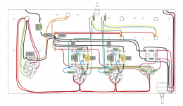
Here's a quick mockup of putting the driver tube in the middle, flipping the output tube sockets 180 degrees, and running the heater wires in the middle of the chassis. The capacitors are now to scale as well. I'm still working on the layout of the power supply section.
For the B+, I have it running from the 39k resistor to the terminal strip, where it connects to the coupling capacitor and 200K Schade feedback resistor before continuing on the the driver tube plate. I figured this was better/simpler than having it run from the 39k resistor to the driver tube plate, and then continue back to the coupling capacitor and 200k feedback resistor.
Also, is it okay to run the other channel's B+ all the way along the front of the amp? Should I take a more direct route (maybe over the wiring). I assume I'd want to keep this away from the heater wires.
For grounding, I've been keeping each channel separate. Should I just connect the grounds near the cathode bias grounds (below the driver tube), or is it fine if I run separate wires back to a common ground (and then connect to chassis ground through an RC circuit).
Thanks again everybody!
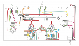
I've attached the most recent layout. (In real life, the signal wires (in purple) will take a more direct approach to the driver tube (rather that up and around), but I drew them like that for clarity. I've also left out the ultralinear/triode switch for now.)
Does anybody see anything glaringly wrong with this layout?
A couple of questions:
- For getting the B+ over to the channel on the right side of the layout, I have the wire running in the front of the amp. Is this okay, or should I have it run on the other side (nearer the heater wires)?
- For the signal wires from the pot, should I use shielded cable for this if possible? And then just ground the shielding at the pot?
- For grounding, I have each channel's star ground going back to a central star ground at the power supply filtering capacitors. For the signal input ground, I currently have that connected to the closest channel ground star ground. Is this okay, or should I run that wire all the way back to the central star ground?
- Currently I have two 100ohm resistors creating a virtual center tap for the heater wires. Good idea or bad idea?
B+ could go between the octal sockets and the tag strips. Now you have the heater wires centrally, keep as much as possible away from them, especially not parallel to them.
Best use shielded cable for signal input. Make sure the input RCA jacks are not connected to the chassis, then connect the shield wires to the jack outer and pot.
Don't connect the pot signal ground like that, run it back to the star.
Virtual centre tap is fine. Just don't leave the heater wiring 'floating'.
Only other thing is the 500 ohm resistors might be better in more free space, but physical (real parts) layout will soon get you a better position.
Alan
...
- Currently I have two 100ohm resistors creating a virtual center tap for the heater wires. Good idea or bad idea?
Just noticed where you have put the 2 x 100 ohm resistors... You have them 'referenced' to the cathode of the KT88 not to the star ground point? Better to move them off the socket and add another tag strip for them. If you turn the 2 100uF 450 volt caps through about 90 degrees anti-clockwise, you could mount them in the space above the rectifier , sorry really cr***y sketch.
Attachments
Thanks Alan for all your help! I'm learning a lot from this.
For the heater grounding, I was just going off the schematics on The Valve Wizard website (The Valve Wizard), and specifically this:
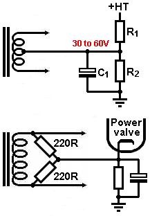
But now that I'm reading more about it, I'm realizing this will elevate the heater voltage rather than just grounding it. That website says that heater elevation can reduce hum, but any thoughts on this?
Thanks again.
For the heater grounding, I was just going off the schematics on The Valve Wizard website (The Valve Wizard), and specifically this:
But now that I'm reading more about it, I'm realizing this will elevate the heater voltage rather than just grounding it. That website says that heater elevation can reduce hum, but any thoughts on this?
Thanks again.
Fair comment, it is a very useful scheme with some types of 'driver'. (Look up SRPP or totem pole where one half of a valve is above the other and there is a difference in cathode potentials.)
But here it is not really necessary, your driver cathode will be at less than 2 volts.
I would build it as a virtual centre tap to ground first, you can easily try it on the KT88 in the future should you want to experiment.
But here it is not really necessary, your driver cathode will be at less than 2 volts.
I would build it as a virtual centre tap to ground first, you can easily try it on the KT88 in the future should you want to experiment.

Yes you are very close.
There is a simple change to make assembly easier, fit the 180 ohm resistors (double triode) in place of the blue wire and then mount the LEDs on the tag strip and ground their cathodes. It does not matter to the circuit operation. (Also I would run those ground wires back to the star, but as you have it should be OK.)
Don't forget you need to ground one side of each output transformer secondary too.
And a general 'tip', use tag strips with more free tags than you need from the layout. That way you have flexibility if something does not bend like you want or you want to make changes later on.
For instance if you had 2 more tags on the central strip, you could mount the 3k resistors there rather than have them 'floating' on the end of the wire. Then add a couple on the strips either side of the KT88s (4.7K resistors on there now) and mount the 'free' end of the 100 ohm resistors there too?
Alan
- Status
- This old topic is closed. If you want to reopen this topic, contact a moderator using the "Report Post" button.
- Home
- Amplifiers
- Tubes / Valves
- KT88 SET internal wiring layout