When I was just born about 1953 my parents bought a really nice new Gramophone. It's a HMV and the model is a G1C1. It's a nice little valve amp in a big cabinet with 3 speakers and a Garrard turntable.
I inherited this baby and when I first got it I often played old very scratched vinyl on it which sounded amazing. But then it developed a nasty cracking sound that wasn't the pots and though the caps were apparently replaced at some point that was probably in the late 60's so I took it to have new caps fitted. However good help is hard to find round here in the Northern Rivers NSW and the only guy who had a look at it was somewhat strange and returned it in worse condition than when I took it to him. So I've decided to restore it myself.
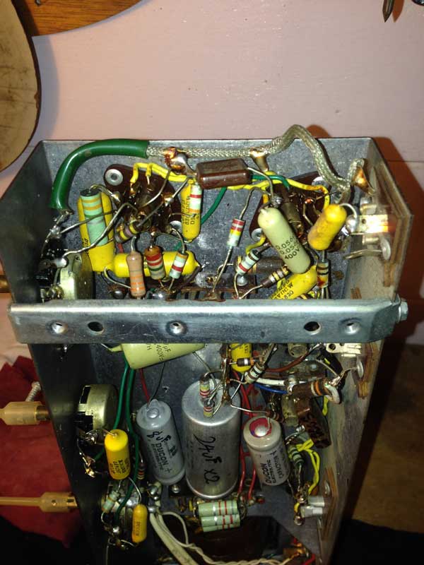
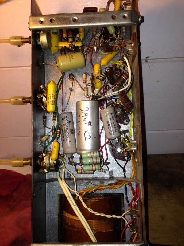
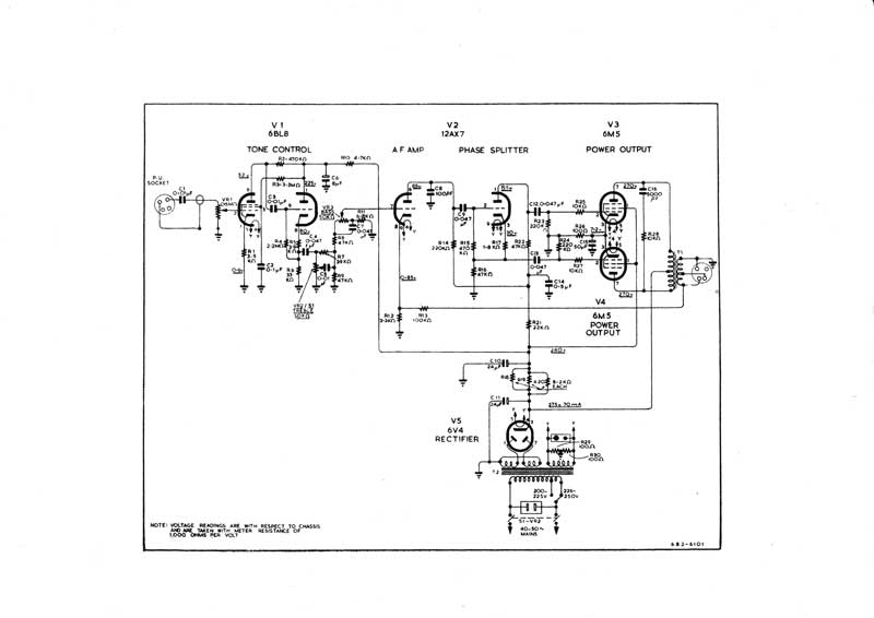
I discovered Kevin Chant's fabulous website and downloaded the schematic and other info for this unit. I have spent a whole day with schematic and multimeter and found that the resistors are pretty close to correct and also the sizes of the two mysterious small value caps that are flat bakelite kind of thing, with no value but Simplex embossed on one side. The birdsnest maze is really something to trace around. So I've ordered the caps and while I was at it I ordered another set and two sets of resistors as well because I think this would make a great little one channel monoblock and I'd like to make a matching copy. It has 5valves, the tone control uses a 6BL8, then it has the 12AX7 for amp and phase splitter, then the power output is handled by a pair of 6M5's and then the obligatory rectifier using a 6V4.
I am wondering whether to do away with this valve and simply use a bridge rectifier but not sure exactly how that would be done. I've done quite a bit of reading on this at the Lenard Audio Institute and it seems this is a mono version of an early Class AB push-pull. It does use negative voltage feedback but someone has substituted a much lower resistance at the end [than the one in the schematic]which may have given it a boost.
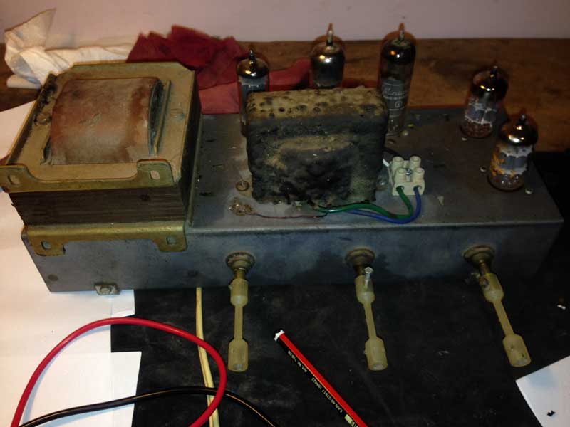
I would like to fit a trimpot there to observe what effect the variation has. I also want to install a bias method if it would be beneficial. Here comes the first problem I face: How to replicate or get equivalent transformers? The parts list quotes T1, Output transformer part no 904-0211 And T2, Mains transformer part no 904-0045 But I don't know where to look to discover the specs of these things. Can anyone give me a clue? The schematic shows the rec tube delivering 275V DC and I assume the other secondary must be 6.3 volts AC to feed the heaters. Is that likely or possible? As you can see I am a rank learner here so I would love some guidance. I'll post some pics below. As you'll see the apprentice may have been let loose on this one. It was sent to the TV repairman just up the hill from where I lived as a teenager.
Cheers. Dan
I inherited this baby and when I first got it I often played old very scratched vinyl on it which sounded amazing. But then it developed a nasty cracking sound that wasn't the pots and though the caps were apparently replaced at some point that was probably in the late 60's so I took it to have new caps fitted. However good help is hard to find round here in the Northern Rivers NSW and the only guy who had a look at it was somewhat strange and returned it in worse condition than when I took it to him. So I've decided to restore it myself.
I discovered Kevin Chant's fabulous website and downloaded the schematic and other info for this unit. I have spent a whole day with schematic and multimeter and found that the resistors are pretty close to correct and also the sizes of the two mysterious small value caps that are flat bakelite kind of thing, with no value but Simplex embossed on one side. The birdsnest maze is really something to trace around. So I've ordered the caps and while I was at it I ordered another set and two sets of resistors as well because I think this would make a great little one channel monoblock and I'd like to make a matching copy. It has 5valves, the tone control uses a 6BL8, then it has the 12AX7 for amp and phase splitter, then the power output is handled by a pair of 6M5's and then the obligatory rectifier using a 6V4.
I am wondering whether to do away with this valve and simply use a bridge rectifier but not sure exactly how that would be done. I've done quite a bit of reading on this at the Lenard Audio Institute and it seems this is a mono version of an early Class AB push-pull. It does use negative voltage feedback but someone has substituted a much lower resistance at the end [than the one in the schematic]which may have given it a boost.
I would like to fit a trimpot there to observe what effect the variation has. I also want to install a bias method if it would be beneficial. Here comes the first problem I face: How to replicate or get equivalent transformers? The parts list quotes T1, Output transformer part no 904-0211 And T2, Mains transformer part no 904-0045 But I don't know where to look to discover the specs of these things. Can anyone give me a clue? The schematic shows the rec tube delivering 275V DC and I assume the other secondary must be 6.3 volts AC to feed the heaters. Is that likely or possible? As you can see I am a rank learner here so I would love some guidance. I'll post some pics below. As you'll see the apprentice may have been let loose on this one. It was sent to the TV repairman just up the hill from where I lived as a teenager.
Cheers. Dan
The input was disconnected while the cracking noise continued so that wasn't the problem. I also plan to fit a better turntable in there once the amp is fixed but maybe if I build a second one there will have to be another speaker box. Here's the schematic. I'm having trouble locating the 6M5 power tubes and looking at the EL84 I see the specs seem almost the same save for the reversing the 9 with the 1 .
Hi Dan,
Sounds like you are keen to restore this amp, and have a good start with the schematic and a basic meter. It will be a significant learning curve for you, and so I'd suggest you initially focus on staying alive (ie. electrical safety), and just getting the original unit operating, before contemplating changes. The experience gained in identifying where there may be bad parts, and gathering useful test tools, and setting up a practical input, and a practical speaker output, and confirming that all stages and parts are operating as originally intended, will imho be invaluable to you.
There are many good references on-line to how to setup and test valve amps - including Classic ANZ Valve Guitar Amplifiers, and https://www.dalmura.com.au/static/Renovating%20PA%20amps.pdf.
There are local forums like aggh and Yahoo! Groups. Aggh has links to local part suppliers, such as for 6M5, and those valves often show up on ebay.
Making any change in a valve amp will typically require a good level of experience and awareness - and imho is best done with an amplifier that is working properly with no faults, and known operating levels and performance.
Ciao, Tim
Hi Tim, I see you are based in Melbourne where I grew up and where this unit once lived. Thanks for your words of wisdom and the invaluable links. I totally agree with your suggestions. I am planning to replace one cap at a time and test in between so I don't compound any unknowns or mistakes.
This was a very sweet sounding unit in it's day and I have great respect for it, humble though it may be compared to much on this site. I am hoping that someone amongst these links may be able to identify the correct output transformer as I suspect mine may have been swapped by the last guy who fiddled with it which might be why it came back with half the volume. You have given me hours of research , thankyou I am most grateful.
This was a very sweet sounding unit in it's day and I have great respect for it, humble though it may be compared to much on this site. I am hoping that someone amongst these links may be able to identify the correct output transformer as I suspect mine may have been swapped by the last guy who fiddled with it which might be why it came back with half the volume. You have given me hours of research , thankyou I am most grateful.

Dan, the replacement OPT may be fine as is. I doubt you will come across an exact spare part easily, but could post on that yahoo group, and aggh, or you may luck it with an ebay item (eg. the whole chassis).
That gram's push-pull OPT for 6M5 would have about 7kohm PP impedance, to match a 7.5 of 15 ohm output speaker, and your OPT can be tested for whether it provides that match. Similar OPT's would be found in quite a few aussie radiograms, as many used 6M5 PP, so may pop up on ebay.
Many faults can cause reduced power output - the key is to work through the performance of each stage to confirm it is working as expected. Certainly an OPT with a different impedance match would affect the feedback level, and often the feedback connection is only reinstalled after the amp checks out on all other fronts.
That schematic gives a few basic dc operating levels to start the process, and then testing would typically move to checking the progress of a sinewave from input to output to determine clipping symmetry and levels, and then you can even go to a spectrum sweep and look for noise floor and spurious peaks from inadvertent feedback.
It's a great hobby if you are keen.
I've been reading much debate about equivalents to 6M5 and with so many opinions based on so much science there is barely agreement from any of the experts.
For instance:
Then we have:
And later
Really? In this last one what is sposed to happen to the wire on terminal 6? None of this stuff inspires me at all though perhaps the method for testing if the valve is OK might be valid. I wouldn't know.
For instance:
The 6M5 is indeed like 6BQ5/EL84, but not as good imho, and I often change the socket connections of radios from 6M5 to suit 6BQ5 because the 6M5 is no longer made and the 6BQ5 is very plentiful.
Patrick Turner.
Then we have:
Hi, The 6M5 Tube = European EL80 was derived from the 8 pin Rimlock Socket EL41 or 6CK5 It is in no way the same as the 6BQ5/EL86. The socket connections are different, and mainly, the 6M5 has a load resistance of 7000 Ohm where the 6BQ5 has 5000 ohms. The 6M5 was used in quite a few Australian Radios, In Kriesler, HMV , Astor and many more. It really had no equivalent in a 9 pin socket. The closest to it is the 6GW8/ECL86 pentode part. The characteristics and voltages are very similar.So is the load resistance of 7000 Ohms. The Filament current is also nearly the same. This means, the same output transformer can be used This tube was made in Australia by Philips, Mullard and AWV (RCA). Also in the US a few companies manufactured it.
it was not popular in europe. The manufacturres most of the time went straigt from the EL41 to the EL84, which was then the most used single ended output tubes in radios.
The Pin connections a
Pin 1=g2, Pin 2=g1, Pin 3=k+g3, Pin4,5 = Heater , pin 6=IC, Pin 7=a, Pin 8=IC and Pin 9=NC.
The 6M5s had a bit of a problem, they tended to draw grid current when they started to get old. I had 2 radios today, where the grid was about 4V positive . The cathode voltage went up to about 11Volts and the tube took a lot more anode current. It also got very hot. It is not a very nice looking tube, specially when used for a long time. The inside goes black and outside the anode inspection holes, a silver layer builds up. The same applied to the EL41.
I hope this helps a bit. If you need more info , Data , history etc, please let me know.
Regards, Horst
And later
Hi Alex,
Before you discard your 6M5 as bad, do a couple of tests. You need a High impedance meter, Either a digital voltmeter or a VTVM.. 1st disconnect the coupling capacitor from the grid of the 6M5. Read the voltage from the grid to ground. you should have zero volts, if your radio uses a cathode resistor on the 6M5 cathode . If it uses semiautomatic bias, then you should have about -6 or similar on the grid. The main thing, you should not have a positive voltage at all. If it is positive your tube is crook. 2nd. If it is zero volts, measure the cathode voltage. this should be about 6 to 7 volts. If it is less, then the valve is weak.
If it is ok, replace your coupling condenser and fit a new one.
If it is faulty, the closest (just about completely identical) tune is the 6GW8/ECL86. No component values need to be altered including the cathode resistor. both have 170Ohm and both tubes draw 36mA anode current. The Gm on both is 10mA/V
It is easy to rewire the socket. Do it in the following sequence
1.) Move the wire from pin 7 to pin 6 (a) 2.) Move the wire from pin 1 to pin 7 (g2) 3.) Exchange the wires from pin 2 and pin 3 (cg3 and g1)
Pins 1,8 and 9 should have no connections. Short pin 9 to ground.(at)
This will give you identical results . If you don't have a 6GW8, then I am happy to send you a new one at no cost.
The 6GW8 is really a very good reliable tube. the triode section is identical to half a 12AX7/ECC83. The tube started to come in to use in big style in the early 60's. It was used a lot in the Japanese amplifiers. (Pioneer , Sansui, Trio etc) . Mostly in push pull in this Tuner-Amps. It got a reasonably bad reputation then, because the Japanese, to get the power ratings up, used it to the limits. It just got to hot and died from shorted grid and from open cathodes. I replaced plenty. During this time I worked at Astor Radio in the service dept. Astor being part of EIL. Did all the Pioneer repairs, and during this time i did them all. (EIL was the Australian importer of pioneer). When the tube was used within its ratings, it performed for a very long time without problems.
Let me know, if you need one, and let me have your mailing address. My email is:
Happy Christmas, Horst
Really? In this last one what is sposed to happen to the wire on terminal 6? None of this stuff inspires me at all though perhaps the method for testing if the valve is OK might be valid. I wouldn't know.
- Status
- This old topic is closed. If you want to reopen this topic, contact a moderator using the "Report Post" button.
- Home
- Amplifiers
- Tubes / Valves
- HMV G1