Hi All.
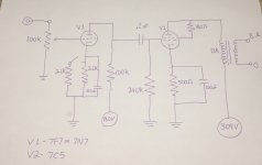
I am building a 7C5 SET amp that has a switch for changing the bias resistor on the preamp tube to suit either a 7F7 or a 7N7, which are pin compatible. These tubes are basically 6SL7 and 6SN7 equivalents respectively, and the 7C5 is a 6V6 equivalent. 2.2K is for the 7N7, and 1.1K is for the 7F7. The 13K:8 Ohm OPT is high for a 7C5/6V6, but it is the best quality single ended transformer I have at hand, and my understanding is that it should give me lower power at lower distortion than the 5-6K primary OPT that is normally used. 1-1.5 watts is enough for my speakers. Please have a look at the attached schematic and let me know if it makes sense. Any comments or advice would be much appreciated. One channel of two is shown.
Cheers,
Tiz
Attachments
artosalo: 50 milliwatts more than a 71A! Perfect. I had a DIY 6SL7/6V6 SET amp, which I sold recently, that used 6K:8 Ohm OPTs from an old console. It had a really lovely midrange and treble, but almost no bass. My experience with using higher than normal primary impedance OPTs has been that bass response improves with the increase in the primary impedance. I knew that my output power would go down with the OPTs I want to use, but I didn’t think it would be by one third. Should be okay with my La Scalas though.
I've always kind of wondered… why these kind of VERY simple designs (and I am definitely not criticizing the simplicity!), don't simply have the final strapped in parallel with a few more of its sisters.
I mean, pretty clearly, the 6V6 equiv. has a (https://frank.pocnet.net/sheets/084/7/7C5.pdf) sweet spot of –12.5 volts grid-to-cathode relative bias for maximum output. The pocnet reference specs a 280 Ω resistor for self-bias.
Simple (simple-minded, perhaps) calculations from the 6V6 spec-shet show that with about 280 V on the anode relative to cathode, it takes a 270 Ω resistor to come toward 45 ma quiescent current.
But then — again, just wondering — I'm curious why one doesn't just put a pair of them in parallel. Clearly at no point will the output section be drawing appreciable current from the stage before… this is a SET, and there's at least –12.5 V (if not –20 V as in the OP's original diagram) headroom before current conduction.
So why not?
Seems obvious.
And except for a different output transformer, doesn't even seem edgy.
Might be able to get a sweet 5+ watts out of a pair, or 10+ watts out of a quad.
Just asking,
GoatGuy
Given current hogging, isn't the obvious solution just “individual cap-bypassed cathode bias resistors”?
The actual quiescent current on each output tube doesn't really matter ALL that much, as long as they're within ±20% of the spec range. Indeed, it would be expected to encounter at least that level of variation from different samplings of tubes, viz a vis their date-of-manufacture, length of prior service, manufacturing variations, and so on.
Each output tube has say a 500 Ω resistor, and as shown a 100 µF cap bypassing it (F–3 db = (2 ÷ 2πCZ) = 6.3 Hz), so that's pretty much OK. And relatively inexpensive 50 V electrolytics, if-you're-a-purist-bypassed with 0.22 µF paper caps, but I wouldn't. For each output… There's no current hogging, for sure, just current sharing. Current 'divide an conquor'.
Again, I'm admitting not being either wise enough or experienced enough to 'suss out why such simplistic SET parallelism isn't regularly employed.
Clearly it COULD be obvious: cost of the output tubes. Or cost of the beefier output transformer. Or cost of the additional power supply filtering current handling. And power transformer. And posibly because of unacceptable levels of zero-signal thermal heat output. Or some combination of the above.
Anyway.
Welcoming your thoughts.
GoatGuy
Again, I'm admitting not being either wise enough or experienced enough to 'suss out why such simplistic SET parallelism isn't regularly employed.
Clearly it COULD be obvious: cost of the output tubes. Or cost of the beefier output transformer. Or cost of the additional power supply filtering current handling. And power transformer. And possibly because of unacceptable levels of zero-signal thermal heat output. Or some combination of the above.
Anyway.
Welcoming your thoughts.
GoatGuy
Eh, could be several (and admittedly valid) reasons to use a single tube for SE.
Often it comes down to design philosophy of wanting as few parts as necessary in the signal path. Cool, I get it. Minimalist stuff has a charm all its' own. Sometimes, this is explained as having better clarity, or soul, or other such words. Whatever, either way, it's simple.
Sometimes an old chassis is being reused, and additional holes may be undesired, impossible, or you just don't plain want to (or cannot due to tools available) cut another hole. Fine, I understand here too- adding sockets may be easier said than done, or not feasible due to space available.
Maybe the builder only has a pair of tubes, and doesn't want to buy more until replacement time? Ok, I suppose this is a valid reason too. With such inexpensive tubes, I usually buy a few pairs to be safe, before committing to a design, but that's just me.
Or, quite simply, maybe the output power they will get is plenty? This is a pretty valid reason too, design choice and dynamics notwithstanding. My personal main amplifier is a flea amp using the 6SN7, and I find the 1~1.2 watts it can give full blast is exceedingly , unlistenably loud, and my 92dB/W speakers do plenty fine at such power levels. It appears to have enough headroom. For the OP, a 7C5 is basically a 6V6, and a triode-strapped 6V6 is one of the more charming tubes there is- It's every bit as nice as a 45 DHT, without the pesky filament-cathode business. If the meager output will work for you, then cool. You have arrived.
My usual choice when more power is needed, is often another type of tube. I've been known to do parallel builds from time to time, but there are so many affordable unsung heroes of the tube world that simply doing something different can be a rewarding enough reason to "step outside the box" and build a different topology, design around a uncommon TV tube, etc.
Last edited:
The La Scalas I use regularly have a sensitivity of 104dB/W/M, so a 800mW amp should be fine. I have several old pairs of output transformers, and most of them have high primary impedances. I used up all the OPTs that I had with 4-6K primary windings a while ago. Also, if 1 watt isn’t enough, are 2 watts really going to make a significant difference? In a SET with parallel tubes, the end result is a doubling of output, which amounts to a 3dB increase in volume.
Last edited:
The OPTs that I am using are Edcors made for Decware’s SE84 amp. I have built a few clones of this amp, which uses EL84 or SV83 as the power tube. My current SE84 clone has very good bass response, especially considering it’s 2 Watt output. I am hoping that I can get similar bass response with the higher primary impedance of these OPTs, although the overall output will be reduced by this higher primary. It seems to work that way for the SE84 amps, with their 13K:8 Ohm OPTs.
You could play around with the operating point of the 7C5/6V6 to optimize the power output with the higher Z OPT.
- Use max B+ on the 7C5/6V6
- Change the bias point (slightly higher/more negative) and use more drive
These two changes could gain back some power, although I have not simulated it or calculated, just ideas.
When I build 2A3 amps, I use 5k OPT's because the distortion is much lower than a 2.5k. I just drive the 2A3 a little harder and it makes up for the higher Z OPT.
THD+N: I have the 7F7/7N7 at a B+ of 180 Volts, but it could easily be 250-270 Volts. The B+ available for the power tubes is at the maximum it can be with the power transformer I have installed. PSUD II puts it at 309 Volts. With the same B+, my previous 6V6 amp had 293 at the plate with 15.6 Volts across a 330 Ohm cathode resistor for 47.3 mA. So 277.4 Volts plate to cathode times 47.3mA is 13.1 Watts dissipation per 7C5. Is that what you mean? The cathode resistor at 500 Ohms, as per the schematic in the first post of this thread, should give me a slightly higher B+ and less mA through each power tube, for a dissipation under 12 Watts.
Yes.
You'll get more voltage swing and lower distortion with increased voltage available to the front end. I find that the 6SL7 (7F7) really wakes up at 250 volts supply, unless ran with a CCS plate load. The 6SN7 (7N7) will do a bit better here, but you would want to drop the plate resistor to get it in a more linear area of the curves at the lower supply voltage.
Increasing the volts is a helpful thing to do here.
Great. I’m going to shoot for 270-280 Volts of B+ for the preamp tubes, and 2300 Ohms and 810 Ohms for the 7N7 and 7F7 cathode resistors respectively.
All chassis work done, all magnetics installed and most of power supply wired.

Here’s the outside. It’s built into an old black file card box, with the lid painted flat nickel.

All chassis work done, all magnetics installed and most of power supply wired.
Here’s the outside. It’s built into an old black file card box, with the lid painted flat nickel.
- Status
- This old topic is closed. If you want to reopen this topic, contact a moderator using the "Report Post" button.
- Home
- Amplifiers
- Tubes / Valves
- 7C5 SET with 7F7 or 7N7 on switch