Is anyone familiar with the 6L6GC/KT-66 push pull amp from his book Vacuum Tube Amplifier Basics? I don't want to use the copyrighted schematic here so I'm hoping someone will be familiar with it. It looks pretty simple; but I'm wondering if maybe it is too simple for really good sound quality since it is from a book of "basics" and would be designed to be easy to build. Nothing fancy, cathode biased output tubes, 12AU7 for a driver/splitter
thanks,
thanks,
There are a lot of great schematics here for PP 6L6GC amplifiers. Simple does not necessarily mean bad. I'm not familiar with the book in question, so I can't offer feedback. Everyone's got a favorite design for this. Lastly, see this thread for reference, well worth the read. Pretty much the definitive design thread for Push-pull 6L6 amps.
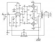
6L6GC AB2
6L6GC AB2
I got permission to copy the schematics here.
I'm trying to decide on doing it as monoblocks or stereo. Edcor has a power transformer with 350 mA but that doesn't leave a lot of room between the 160 mA per channel that is listed and the choke only handles 300mA so I'd still need two of those. I'd also need to add another 6.3 transformer as the 6A would be too close for 4 KT-66 tubes if I decided to run those along with the 12AU7
I'm trying to decide on doing it as monoblocks or stereo. Edcor has a power transformer with 350 mA but that doesn't leave a lot of room between the 160 mA per channel that is listed and the choke only handles 300mA so I'd still need two of those. I'd also need to add another 6.3 transformer as the 6A would be too close for 4 KT-66 tubes if I decided to run those along with the 12AU7
Attachments

Lets begin with I'm no expert. Now that that is out of the way....
I would say build it.... as mono blocks. Yes you could get a larger power transformer and choke but then you may end up with a larger, heavier than you probably want amplifier (these days weight plays a role for a lot of what I do).
If it were me I would convert to fixed bias and given the choice the 12bh7 over the 12au7. Maybe you could sub a 6cg7.
It appears the phase inverter has been optimized for a particular value, most likely for linearity at the chosen point.
Input capacitor, grid resistors on the output tubes, filter on the cathode of the input tube. Looks like some thought went into it to me.
As mentioned before there are tons of 6l6PP circuits out there but this looks fine to me.
Andrew
Rubbish. Parts count has little to do with how "Hi-End" something is. Parts quality and intelligent engineering is much more important.IMO, HiEnd is back proportional to the number of composit parts....
For the design in question, however-
I frontline that cathode bypass/feedback arrangements on the input tube. It would be better to have the feedback and cathode resistance series connected with the usual cathode resistance on top of the stack, with only the upper cathode resistance bypassed, and the junction of the upper/lower resistor being the point that the feedback resistor feeds to.I can dig up a diagram if I didn't explain this very well.
I don't think that the 12AU7 is a good choice here, and not just for it's lack of linearity. It will have a best case gain of ~14 or so in most real world applications, and this may be insufficient to drive the outputs to full power, especially with feedback. You would be better served with a "hotter" input stage, like the 6N1P, 12AT7, or something similar. Both will work with some parts value adjustment, and would give better headroom. A 6N2P or 12AX7 (or, even a 6SL7) would be a better choice. If using the 6N2P or 12AX7 you can leave the cathode unbypassed for better linearity without excessive gain.
If you run a hot enough preamp this may not be an issue. If you have a hot preamp, and a couple 6CG7, I would use them instead. Much more linear tube, and will work much better.
It will have a best case gain of ~14 or so in most real world applications, and this may be insufficient to drive the outputs to full power, especially with feedback.
If you run a hot enough preamp this may not be an issue.
A+. Is an input sensitivity specified for this amp? Since the voltages on the driver aren't shown it's tough to estimate the cathode biasing voltage there to speculate on the expected input signal voltage. Looks like near 100% class A operation, ...?
Last edited:
It's pretty hard to tell without parts values, but going for an "educated guess" of sorts, with 400 volts supply and UL connection, you will need to run -25~ or so volts G1 at least on the 6L6 to keep it in a reasonable dissipation area, so even a 2 volt peak input with a fully bypassed cathode on the first 12AU7 will just barely cut it as far as swinging enough signal.
If it were me, I would probably throw a 12AT7 at the problem, should give you a gain of ~32 or so without anything special going on, and will have an easy enough time swinging into the grid capacitance of the connected outputs. There are several other medium-to-moderate Mu tubes that will also work here.
Again, this all depends on how hot your source(s) may be. Or, if you have a preamp that has a bit of gain that you may intend to use with it. Most all my sources (other than the TV) struggle to put out more than 300mV RMS, and I usually shoot for full-output at 1 volt input in most cases, since nowadays consumer level audio comes out at -10 dBV, 0.316 RMS, 0.44Peak, which is 0.89 peak-to-peak.

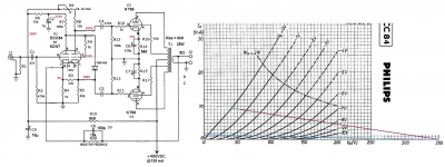
How about like this ? Just an idea
Mona
That is an impressive rework for 'just an idea'. I'm continually trying to learn more about how they work but I'm still at the point that to be able to look at a schematic and go "change this this and this" is a bit like watching magic.
thanks
^ there you go!
It'll take about 3 volts of input signal, which is pretty high. Needs a good preamp that will put out around that much, or it needs a different input tube and some parts changes.
I was figuring with Monoblocks I'd probably put the amps near the speakers and a preamp of some sort on the shelf for control but would have to look at what ones put out around that.
Last edited:
A nice little preamp with a gain of 10~15 or so is super simple to do and will give you a common spot to have all your sources and volume control anyway ")
The Salas 6V6 line preamp comes highly recommended, and something similar with a single 6SN7 or 6CG7 would also be hard to beat!
The Salas 6V6 line preamp comes highly recommended, and something similar with a single 6SN7 or 6CG7 would also be hard to beat!
One the input stage a single cathode resistor bypassed with resistor in series with bypass capacitor yielded a slightly lower distortion figure. The problem with higher gain tubes is they have a higher plate load resistance. A tube may have higher gain, but with a too low loading resistance the output level goes into distortion sooner resulting in a lower usable output level. Cathode bias is better for rolling tubes. If fixed bias is used the bias would need to be adjusted depending on the type output tube in use. It would require at least an audio generator and oscilloscope to adjust bias for least amount of waveform distortion. The output tubes each having their own cathode resistor is recommended for KT66 output tube use. Monoblocks are usually preceded by a control center pre-amp with volume and tone controls, tube or solid state. A control center pre-amp should easily provide enough 2 - 3 volt drive.
Swapping Phase Inverter Tube Types
I've been busy so I'm a bit late with this last note on swapping out phase inverter tube types. When the phase inverter is a simple split triode voltage gain of the inverter is essentially zero. Also, the available output voltage level is significantly less than a normal stage because available (B+) voltage for the tube to swing is split between the plate and cathode.
The input grids of push-pull output tubes require a certain voltage level for full output. Higher power output tubes usually require higher input grid drive voltage. Directly driving power output tubes with a simple split triode phase inverter is limited to about a 30 watt output level maximum. This is because the split triode provides reduced drive due to the available voltage swing split between the inverter plate and cathode.
With all this in mind you want the maximum amount of low distortion drive voltage possible. Otherwise you will not realize full output power because the phase inverter goes into saturation distortion before the output tubes do.
The circuit in question is simple, but provides high quality low distortion audio providing high quality output transformers are used. A 12AX7 may provide more gain, but cannot provide the output level necessary to drive the output tubes to full output. I know this for a fact because I tried it. With a 12AX7 the inverter goes into distortion before the output tubes saturate. The reason is due to the high impedance of the 12AX7 which loads down more severely and thus goes into distortion sooner. The 12AU7 or 12BH7 has a very low impedance less affected by loading. I check my circuits using a low distortion audio generator and HP distortion analyzer. The loading effect comes into play with higher gain tubes. Higher gain tubes usually have a higher impedance. The higher the impedance the more they are affected by loading.
Swapping output tube types is more forgiving. The output stage circuit values will work with several different type output tubes. If you start swapping out tubes driving the output tubes without means to measure the results, you may be inducing distortion. You will not know for sure if you are hearing differences in output tubes or if circuits driving the output tubes are distorting.
The way to get more output tube grid drive is to add a stage between the phase inverter and output tube input grid. This of course complicates the circuit and projects in the book are intended to be as simple as possible.
- Home
- Amplifiers
- Tubes / Valves
- EJ Jurich PP Monoblock