While going thru the Do It Yourself Audio forum (6SN7 Flea Amplifier Project), I found this rather interesting circuit. It attempts to equalize the cathode currents in a PP pair of tubes. It would be useful for a PP amp, especially when the OPT is a toroid where very little DC bias in the OPT core could saturate it.
This is the same Blumlein who patented what became the ultralinear circuit 15 yrs before it was called that.
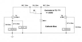
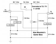
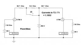
To analyze the circuit I assumed triode connected KT66's, just as they were in the original Williamson, with the following constants for the simulations-
Plate volts 300 Volts
Grid Bias -36 Volts
Plate Current 36 mA
MU of 8
For another KT66 not the same so that the circuit would be unbalanced, the plate current used is 30 mA. On the simulations that tube is labeled KT66 X.
For the OPT primary resistance I used the numbers I had measured for a Hammond 125E sometime ago. That would be 80.7R & 86.6R. The primary is wound serially so the halves are different. Obviously, not a HIFI OPT. The switch labeled 'Z' allowed checking if the primary half differences would affect the results. In the fixed bias cct the difference measured was 0.55%.
The rest of the simulations were done assuming equal halves of the OPT primary.
For the fixed bias simulation the unbalance looks like 18.52%. That is about what we would expect when the tube current spec used in the simulation differs by 20%.
Ordinary cathode bias on its own is a great leveler since it is Negative Feedback at DC. The FB is almost 100% at DC, much like a cathode follower. The only other resistance that interferes with the FB is the DC resistance in the OPT primary. So in this case the NFB at DC is ~90%.
For the cathode bias simulation the unbalance looks like 2.02%, a large improvement.
TheAlan Blumlein bias circuit needs some drop across an extra cathode resistor in order to develop some feedback for the correcting circuit. I simply used another 700R resistor, but anything within reason could be used. It does use up some of the B+. For the Alan Blumlein Garter bias simulation the unbalance looks like 1.0%.
Beyond a few extra parts the only penalty appears to be the extra power in the added cathode resisters. Is it worth it? Maybe, but interesting just the same.
Some may have conflicting opinions.")
To analyze the circuit I assumed triode connected KT66's, just as they were in the original Williamson, with the following constants for the simulations-
Plate volts 300 Volts
Grid Bias -36 Volts
Plate Current 36 mA
MU of 8
For another KT66 not the same so that the circuit would be unbalanced, the plate current used is 30 mA. On the simulations that tube is labeled KT66 X.
For the OPT primary resistance I used the numbers I had measured for a Hammond 125E sometime ago. That would be 80.7R & 86.6R. The primary is wound serially so the halves are different. Obviously, not a HIFI OPT. The switch labeled 'Z' allowed checking if the primary half differences would affect the results. In the fixed bias cct the difference measured was 0.55%.
The rest of the simulations were done assuming equal halves of the OPT primary.
For the fixed bias simulation the unbalance looks like 18.52%. That is about what we would expect when the tube current spec used in the simulation differs by 20%.
Ordinary cathode bias on its own is a great leveler since it is Negative Feedback at DC. The FB is almost 100% at DC, much like a cathode follower. The only other resistance that interferes with the FB is the DC resistance in the OPT primary. So in this case the NFB at DC is ~90%.
For the cathode bias simulation the unbalance looks like 2.02%, a large improvement.
The
Beyond a few extra parts the only penalty appears to be the extra power in the added cathode resisters. Is it worth it? Maybe, but interesting just the same.
Some may have conflicting opinions.
Attachments
For a given voltage drop about twice as effective as regular cathode series feedback, like you already simulated, and it has absolutely nothing to do with Blumlein, like leadbelly wrote. See
https://www.diyaudio.com/forums/tubes-valves/313318-origin-called-blumlein-garter-2.html#post5209648
since you are apparently incapable of using the forum's search function yourself.
https://www.diyaudio.com/forums/tubes-valves/313318-origin-called-blumlein-garter-2.html#post5209648
since you are apparently incapable of using the forum's search function yourself.
Last edited:
I didn't expect so much flack.
Perhaps in response to your earlier comment:
Good for you. What will your next trick be?
Jus' sayin.
Not sure how to change the title. Let me know.
 No worries, I will change the title and edit the texts for you. Please let me know if they turn out ok.
Start with whatever self bias voltages you get for the individually self biased cathodes.
Average those two bias voltages (perhaps 35V).
When you change to the Garter circuit, with 2X the total resistance in the cathodes , you need to increase the B+ by (the average of) the original amount of bias voltages (perhaps 35V).
If you do not do that, then the plate resistance of the Triode wired KT66 will cause the plate current to change quite a bit.
The KT66 plate resistance with 50mA plate current, may be about 1.7k.
35V B+ reduction / 1.7k = 20mA change in plate current.
Under the 35V change of Vplate to cathode, the plate resistance will change quite a bit.
And, it will not change in an equal amount in the two tubes, unless the tubes are quite well matched, both quiescently and dynamically.
Some tubes will match better when you use the Garter circuit, and some will not match as well. But to make a fair conclusion as to how well it works to balance the currents of the tubes you test, you do need to increase the B+ by an appropriate amount when testing the Garter mode. Otherwise, even if the plate currents now match, you will end up with an amplifier that has less max power out, and that has a lower damping factor.
Last edited:
DAK808,
It is not surprising that the AA151 with Garter Bias sounds very similar to the original circuit.
The original circuit uses Global negative feedback from the OPT secondary to the driver tube cathode, then split load invertor, and push pull Ultra Linear EL84 outputs driving the OPT primary. The global negative feedback would retain most of the original damping factor of 10 when Garter bias is used.
The bias voltage of the EL84s are small (not like a typical KT66 bias), so the plate to cathode voltage is not reduced significantly by the Garter Bias. The EL84 plate resistance in Ultra Linear mode is much higher than a triode wired KT66. The result is that the EL84 plate current is not significantly changed as a result of the small change of plate to cathode voltage when adding Garter Bias circuitry.
A push pull output with triode wired KT66s and no negative feedback would be much more affected when using Garter Bias, unless the B+ was increased to keep the same plate to cathode voltages.
It should be noticed that if one of the output tubes shorts, or otherwise draws unusually large current, it will over-stress the other tube that has Garter Bias.
Last edited:
The biasing cct is at DC so a pentode, whether wired as pentode or UL acts as a triode so far as operating point is concerned.
All reactances in the cct that would cause a pentode with an OPT as a load to operate as a pentode are gone at DC. So at DC the high rp of a pentode does not apply.
My thoughts, anyway.
All reactances in the cct that would cause a pentode with an OPT as a load to operate as a pentode are gone at DC. So at DC the high rp of a pentode does not apply.
My thoughts, anyway.
Changing plate to cathode voltage on a pentode wired pentode causes very little change of plate current.
But changing the screen to cathode voltage on a Pentode wired Pentode Will change the plate current. And that means the Garter Bias as it is commonly implemented will change the plate current, unless you raise the screen voltage by the appropriate amount (the loss of screen to cathode voltage caused by the Garter Bias circuitry voltage drop).
Of course you can use individual constant current sinks in the cathode circuits, but then there is no reason to use the Garter Bias modification.
Would someone Please explain if and how the cross coupled cathode bias on AB push pull cause more than double less efficient biasing than normal cathode bias?
I have read somewhere that very high bypass capacitors are needed to prevent the g1 voltages rising on long notes but doesn't the circuit "self balance" all the time when cathode current tries to increase and increased -Ugc limits the Ic?
I have read somewhere that very high bypass capacitors are needed to prevent the g1 voltages rising on long notes but doesn't the circuit "self balance" all the time when cathode current tries to increase and increased -Ugc limits the Ic?
- Home
- Amplifiers
- Tubes / Valves
- How effective is the Garter Bias Circuit