Hi All.
I have a few output transformer pairs that have three wires on the primary, and would like to know how to tell the difference between a push-pull OPT and a single ended OPT with an ultralinear tap. I have been buying OPTs at electronics surplus stores that often have no wiring diagrams or any other documentation, and are not in an amp either, making identification difficult. The pair I would like to use in my current 6V6 junkbox amp project has a centre tap on the primary that is at roughly 50%, and they appear to be gapped. The measured ratio of the transformer is 8:5200 Ohms, so its a pretty good match for the 6V6. Any advice would be much appreciated.
Thanks,
Tiz
P.S. Thanks Jazbo8!
Last edited:
It's pretty simple, you can measure the primary inductance of the OPT in question with a meter while applying some DC current on the secondary winding, e.g., with a lab power supply and a pot + resistor. The inductance of the PP OPT will collapse pretty quickly, while the SE UL OPT will remain pretty constant up to say 20-50mA depending on its rating.
SE will be "gapped". If you remove the banding, the whole bunch of I lams come out. A P-P transformer has the Es and Is interlaced, they don't come out easy.
Don't actually take the iron apart. The gap may be carefully adjusted. Peek in the corners and see what you can see.
Different processes:
A 50% UL tap is unfashionable. Winding resistance is not an exact guide, but voltage tests with an AC source will tell if the 3rd lead is dead-center (P-P) or offset.
The Plate lead is "usually" Red. If resistance shows this is the CT, it is P-P.
Attachments
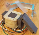
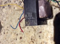
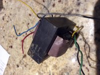
PRR: The voltages are very close to equal between the sides, and the ends of the winding are blue and yellow. The centre tap is red. The OPT looks gapped though. I have attached a couple of photos. The E and I portions are definitely separated. There is no interleaving. The bandings have been removed before, so I took them off for the photos. The E and I portions stay together.
Attachments
Last edited:
Jazbo8: Just to clarify your suggested testing procedure, I have attached a drawing. Is this correct? Also, John Stewart noted that disconnecting the DC source will generate a high voltage spark that could damage the inductance meter, and that the meter should be disconnected before the DC source once the test is complete.
Attachments
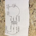
Yup, you got it. And yes do be careful with the connections, don't disconnect anything while testing. I would set the pot to its maximum position, switch on the PS, then gradually turn the pot while reading the inductance on the meter. Let us know how it works out. Since you are just trying to ID the OPT's, you don't really want to heavily saturate the core, so just apply enough current to see some drop (say 20%) in the inductance then you know it's a PP type, after that, turn the pot all the way up again, and switch off the PS.
..the ends of the winding are blue and yellow. The centre tap is red. The OPT looks gapped though.....
It does seem to be a Push-Pull with a gap. Odd.
Blue-Red-Yellow is very typical of P-P.
Perfect push-pull needs "no" gap. Push-pull is never perfect so the designer accounts for "slight" unbalance. Often fully-interleaved is still OK. E-I construction always has an air-"joint" where the Es and Is overlap. For more unbalance they insert 3 Es one way, 3 Es the other way, repeat until full. But yours is all-one-way, zero overlap.
Other thought is that this is for an AM transmitter (such as old CB radio). One side of primary to an SE audio power tube, other side to the RF final stage to smack the audio onto the radio wave. The DC unbalance may be large, especially in reception.
I did the test suggested by jazbo8. I ended up using a 6.5 Volt, 30 mA wall-wart, a 250 Ohm resistor and a 10K Ohm pot. This gave me a maximum of 26 mA into the OPT I tested. With the 10K Ohm pot turned down so that it presented no resistance, and the full 26 mA through the OPT, the inductance stayed roughly the same. The OPT doesn't have a lot of inductance in the primary, with 6.6H measured prior to connecting it to the testing circuit. When I attached the test circuit, and with the full 26mA on the OPT, the inductance went up to 7.4H and jumped around within a range of about .1H while slowly falling overall until it reached around 6.6H. After about 10 minutes, the inductance was at about an average of 6.5H, while still jumping around within the same .1H range.
Is it prudent to test again with a circuit that will put a higher total mA through the OPT, or is the 26mA sufficient to ascertain that this is indeed a single ended OPT with a 50% Ultralinear tap?
Is it prudent to test again with a circuit that will put a higher total mA through the OPT, or is the 26mA sufficient to ascertain that this is indeed a single ended OPT with a 50% Ultralinear tap?
It appears that the core did not saturate at 26mA, so it might be rated for higher current, in any case, I think it's safe to say it's a SE UL OPT. But just to make sure, use the same setup and test a known PP OPT to see if you can get a drop in the inductance when the current is cranked up.
This from John Stewart:
"With regard to the test suggested on DIY, 10-50 mA on the secondary will have next to no effect at all. The test current needs to be applied to the primary where it would be a problem for a PP OPT. But could be applied to the secondary if the current was increased so that the same magnetic force resulted in the core. The turns ratio is about 25:1, so as a first order guess the applied current would need to be in the order of 25X that 10-50 mA."
I'll try the test again with the windings switched and report back.
- Status
- This old topic is closed. If you want to reopen this topic, contact a moderator using the "Report Post" button.
- Home
- Amplifiers
- Tubes / Valves
- Identifying output transformers: single ended with ultralinear tap or push-pull