The distortion from the voltage amplifier (being an op-amp, and a good one at that) is lower than the rest of the amp. I have not measured the distortion coming from the phase splitter itself. Spice simulations suggest it's pretty low- about .05%, but I'm not sure how much I should trust this. The J112 is not really designed for linear operation like this- it's a common input switch (hence why I have it in stock).
I may try the differential feedback from the OPT secondary to the driver tube cathodes- could work quite well. I would assume that the feedback resistor would then become the ground reference for the OPT secondary.
I definitely am not a huge fan of how many coupling capacitors I'm wrapping feedback around. I spent considerable time trying to figure out a way to DC couple this, but didn't have a lot of success. I've never seen this sort of JFET concertina phase splitter employed in an amp before, so it would be quite interesting to see how it would perform without feedback around it. I will say that the few JFET-based designs I've heard sound quite good.
As I mentioned earlier, the distortion numbers look promising. 0.2% is pretty good, and if I can get around this LF instability then I should be able to apply significantly more negative feedback, since I haven't run into HF instability issues yet and I suspect I could get away with about 15 dB of feedback with the Hammonds. If anyone has past experiences with how much feedback they could get away with using these transformers, I'd be very interested to know. I've seen some projects where people have worked in 15 or 16dB of negative feedback around a Hammond 1650HA, though I'm not sure how well this will translate to the larger 1650P.
My amp has a mosfet concertina phase splitter directly coupled from the preceding triode voltage amplifier, and driving the output tubes in pentode mode, so only one pair of coupling capacitors in the loop. Because it is essentially operating as a source follower, distortion is very low due to local feedback. The JFET should be similar.
I have used the differential feedback before, it worked fine (yes the ground reference is through the feedback resistors). Only hassle is that you need a two channel scope with differential mode to measure the output properly, otherwise you can only look at half the signal. Can make setting HF compensation capacitor problematic with only a single channel scope.
I have used the differential feedback before, it worked fine (yes the ground reference is through the feedback resistors). Only hassle is that you need a two channel scope with differential mode to measure the output properly, otherwise you can only look at half the signal. Can make setting HF compensation capacitor problematic with only a single channel scope.
Time for an update.
I think I took care of the LF stability issue. I tried the differential feedback, but I was not happy with it. Distortion seemed to go up. I'm not completely sure why this is, but my guess is that it's got to do with the rather odd secondary configuration of the Hammond output transformer.
The thing that kept bugging me is that I should be able to make this work with the three coupling capacitors. I tried replacing C1 with a 22 nF capacitor (I calculated a rolloff at around 22Hz for this), but low and behold, oscillation still there. Took a break, walked the dog, etc. I redid the math I should have done prior to building it, and realized that with .22uF capacitors between the driver stage and the output stage, my cutoff was at around 7.5 Hz. I had a couple of 68 nF 715P caps on hand that I replaced them with- this yields a cutoff around 23 Hz. This seemed to kill the LF oscillation, and the feedback should ultimately widen my response curve significantly so the amp will be flat down to 20Hz.
I've got about 16dB of feedback applied. Open loop gain is around 80, closed it's around 13. This may be too much feedback.
Amp is rock-solid into a resistive load. Good. Let's put it on the AP and look at its noise and dist- oh. Just connecting the amp to the AP box through a not-so-short cable was enough to cause parasitic oscillation when driven. I tried putting a .22 uF capacitor in parallel with the dummy load, and even with no input signal applied we have about 5-10 watts of RF power. Not exactly the best thing on Earth for a tweeter. More work to follow. I have a feeling I might have to drop my feedback down a few dB. Haven't gotten an accurate noise floor measurement yet, but it looked mostly like white noise on the scope- nothing that suggests grounding issues.
Now to figure out how to kill the HF oscillation- I wasn't trying to build a transmitter here. Any capacitance in parallel with the feedback resistor seems to make the problem worse. I'm thinking about a zobel network right after C1 could help.
Attachments
Time for another update
More testing has ensued. By tapping the feedback from the 4 ohm secondary and dropping it down to 14dB of negative feedback, I can't make it oscillate at high frequencies with a .047uF capacitor in parallel with the dummy load. That said, when I try an actual speaker as a load, LF oscillations are back. Obviously it isn't really stable at low frequencies- time to look at that a bit.
Once I get it stable, my plan is to spend some time throwing whatever loads I can at it to try and make it oscillate. It must be unconditionally stable.
Alright, I have two brand-new driver board ideas that could solve the problem.
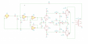
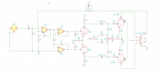
The solution that doesn't involve cheating is what you see in the attached schematic. One op-amp handles the input (and GNFB connection), while the other two are configured as a traditional balanced line driver. The op-amps can be whatever you choose. A TL074 is shown in the schematic, but the AD713, NE5532, OPA604, or whatever will work fine. I ran the simulations with an AD713 because the model is bundled with LTspice. I haven't tried any original API 2520s, but I suppose those would work as well if you're willing to spend about $1200 on the driver board...
If you want to cheat, the second two op-amps could probably be replaced by a THAT1646 to split the phase.
Attachments
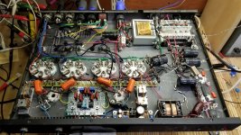
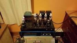
(Theoretically) done. I neglected to take pictures of the underside before I closed it up, but it's not that different from the last pics aside from some nicer lead dress.
There's about 17 dB of negative feedback, and the amp has about 25dB of gain- probably a bit more than necessary, but given that noise isn't an issue, I'm not going to touch it. I was surprised by the fact that the feedback resistor didn't need a capacitor in parallel with it- I couldn't find any value between 22 and 900 pF that didn't make the amp less stable. It is rock solid into a resistive dummy load. When I put a 100 nF capacitor in parallel with the dummy load, it remains stable. It does not like having a 220 nF cap in parallel with it, however, the 3.3uF is just fine.
All that said, I could not get it to oscillate into a speaker. I tried three different test speakers, and while I never went to full power with them (even wit earmuffs it's too loud), I got pretty close and the output was clean. Any other stability tests you guys like to do?
So what does it sound like? IMO, it sounds pretty good. It's a tiny bit on the bright side, but even with my rather bright Elac 510s, it's not bad. It sounds very accurate and clean. I still need to make a 1/8" purpleheart plate to cover the screws on the left side of the front, and I still need to decide what knobs I want to use.
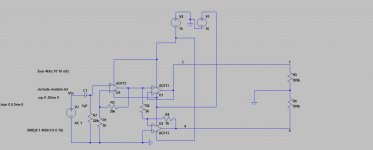
And the noise? Depends. The AP tells me that one channel is -75 and the other is -65dB, but I can't see a difference on the scope. With 87dB efficiency speakers, I can hear a tiny bit of noise if I hold my ear up to the tweeter, but it's more than quiet enough for me. Distortion is about .35% at 2kHz, and drops to .15% at 20kHz. At 30Hz, it's around .35% as well. Not half bad. The schematic above is not correct- the feedback resistor is an 82.5k, and there's a mistake in the phase splitter design. Attached is the correct drawing in LT Spice.
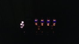
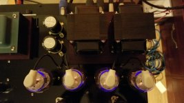
Also, the camera makes the 0D3 tubes look bright white rather than the violet they actually are.
There's about 17 dB of negative feedback, and the amp has about 25dB of gain- probably a bit more than necessary, but given that noise isn't an issue, I'm not going to touch it. I was surprised by the fact that the feedback resistor didn't need a capacitor in parallel with it- I couldn't find any value between 22 and 900 pF that didn't make the amp less stable. It is rock solid into a resistive dummy load. When I put a 100 nF capacitor in parallel with the dummy load, it remains stable. It does not like having a 220 nF cap in parallel with it, however, the 3.3uF is just fine.
All that said, I could not get it to oscillate into a speaker. I tried three different test speakers, and while I never went to full power with them (even wit earmuffs it's too loud), I got pretty close and the output was clean. Any other stability tests you guys like to do?
So what does it sound like? IMO, it sounds pretty good. It's a tiny bit on the bright side, but even with my rather bright Elac 510s, it's not bad. It sounds very accurate and clean. I still need to make a 1/8" purpleheart plate to cover the screws on the left side of the front, and I still need to decide what knobs I want to use.
And the noise? Depends. The AP tells me that one channel is -75 and the other is -65dB, but I can't see a difference on the scope. With 87dB efficiency speakers, I can hear a tiny bit of noise if I hold my ear up to the tweeter, but it's more than quiet enough for me. Distortion is about .35% at 2kHz, and drops to .15% at 20kHz. At 30Hz, it's around .35% as well. Not half bad. The schematic above is not correct- the feedback resistor is an 82.5k, and there's a mistake in the phase splitter design. Attached is the correct drawing in LT Spice.
Also, the camera makes the 0D3 tubes look bright white rather than the violet they actually are.
Attachments
I was surprised by the fact that the feedback resistor didn't need a capacitor in parallel with it...
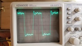
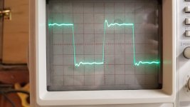
Check with 5...10 kHz square wave and some 10 W out. How does the output signal look like ?
The 10kHz square wave wasn't as clean as I would have liked, though I've seen worse.
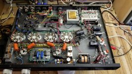
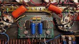
Ultimately I found that a 5 pF capacitor was about all I could get away with. It's not awesome, but it's better and I still couldn't get the thing to oscillate into a speaker. It's stable with a 100nF capacitor in parallel with the resistive dummy load as well. The ugly square wave is without the 5pF cap, the other one is with it installed. Also shown is what the inside looks like, and what the new driver board looks like.
Ultimately I found that a 5 pF capacitor was about all I could get away with. It's not awesome, but it's better and I still couldn't get the thing to oscillate into a speaker. It's stable with a 100nF capacitor in parallel with the resistive dummy load as well. The ugly square wave is without the 5pF cap, the other one is with it installed. Also shown is what the inside looks like, and what the new driver board looks like.
Attachments
H713,
Your experience mirrors mine with Hammond output iron. When secondary is configured for 4 and 8 ohm outputs, I have never been able to pull feedback from the 8 ohm tap for more than about 10 dB feedback or else amp goes unstable easily. I have had much better luck pulling feedback from 4 ohm tap and in that case I can apply up to 18 dB with no problems, but still there was some significant HF phase shifting up above 15 KHz that required fairly aggressive HF step filtering to keep the amp stable.
Did you try a Zobel and what was the result? Where was the 5 pF cap connected? I'd like to see the overshoot a bit smaller on those square wave tests.
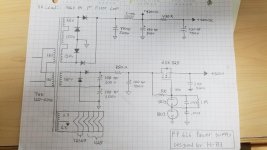
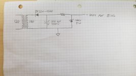
Attached is an updated schematic of both the power supply and the audio stage. 5 pF cap is in parallel with the feedback resistor.
I did briefly try a Zobel on the output consisting of a .1uF cap in series with a 150 ohm resistor- didn't calculate this, just as a test. I didn't notice much difference. I may revisit this later.
I agree that the overshoot isn't awesome. I'd like to get it better. I'm all ears if anyone has suggestions.
IMO, the Hammond iron is pretty good. When I built my last amp, I found that the Edcors didn't allow for nearly as much feedback. That said, I made a real mess of the grounding and wire dress (first big point-to-point layout), so that may have been the real problem.
Kward,
I read your AK threads on your 6L6 amp and both 1625 amps- Extremely helpful. Beautiful looking amps as well. Big thanks for those threads; they've been a good resource.
There is one other major improvement I'd like to make to this amp- Each channel has one AD713 op amps dedicated to it, which means that each chip has one unused op-amp in it. This amp really, really would benefit from a balanced input. In my main system at home, it's dead silent. I tried it in another system using a crappy M-Audio interface, and there was some annoying digital noise. I had a Quested/Omniphonics amp that exhibited the same issues with that interface when using unbalanced cables. Switching to balanced cables solved the problem.
One of the nice things about the purpleheart spacer under the power transformer is that if the transformer ever were to fail, it's easy to make a substitute transformer look perfectly normal by simply making a new spacer. The existing power transformer is a tiny bit borderline- it's what I had on hand, and it gets pretty warm after a few hours of use.
Attachments
Grid stoppers might help with the 12SN7, I could try it. There is, however, a 3K grid stopper on each of the power tubes.
One thing that isn't visible in the schematic (my mistake) is a 50K linear volume pot. Somewhere I have some 10K linear Allen-Bradley pots I'm going to put in there eventually, I just need to find them. Really, since they're individual channel controls, they're more useful as a mute switch than anything.
This amp is remarkably quiet with an open input- quite nice. It is not a high input impedance, but I'm working on a transformer balanced buffer preamp to drive it (matching color scheme and everything).
I know the noise figures I stated aren't truly amazing, but you pretty much have to have your ear up against the speaker drivers to hear it at all. I suspect both channels are realistically about -75dB, perhaps better. I might try to quiet it down even more if I was going to use it with some 105dB sensitivity Klipsch horns, but if I had a set of those I'd be building a SE amp.
OK, still it is advisable to add a RC low pass filter just to avoid problems. You can expect issues (for certain with high bandwidth devices) if you don’t limit.
Of course I noticed grid stoppers on the power tubes but that does not compensate the lack of grid stoppers on the 12SN7.
Of course I noticed grid stoppers on the power tubes but that does not compensate the lack of grid stoppers on the 12SN7.
Last edited:
12SN7's and 1625's - a man (I only assume based on demographics; please forgive me if incorrect) after my own heart.
WRT stability issues, low frequency instability not caused by inadequate power supply decoupling is caused by a lack of a single dominant pole (actually a "zero", but if you understand the difference, you'll know what the problem is). This is completely analogous to op-amp theory with Bode curves and dominant poles, just flipped left for right. The optimum place for a dominant "pole" (actually "zero", yadda yadda) is at the output valves' grids. Choose this time constant to dominate all other RC time constants *and* the output transformer's primary inductance's highest values (at maximum voltage) for best overload recovery, and yes that matters more than most folks might guess. Clipping happens.
High frequency instability really can't be dealt with successfully in valve amplifiers with a dominant pole, and ad hoc solutions are time honored and painful. Both this and the low frequency issues around sliding transformer primary inductance are good resons why sane people don't try to make multi-stage pentode output amplifiers with long loop feedback. Folks did it in the 1950's because they had to; we don't have to.
All good fortune,
Chris
ps: output Zobels (use 0.1uF and 10 Ohm), grid stops and g2 stops everywhere aren't accessories, they're essential. Vacuum valves work just fine into the 10 or hundreds of megaHertz and care not a tiny bit about our drawings on paper.
Last edited:
Seems the current splitter solved the time delay issue.... the phase splitter design. Attached is the correct drawing in LT Spice...

Seems the current splitter solved the time delay issue.
Yep. And now I've got a couple boards I can use to add a balanced XLR output to my function generator.

When I wired the amp I neglected to put 150 ohm resistors on the screens- that will get added when I have a chance. I like having them as they seem to provide some protection in the event of a screen grid short, not to mention the improved stability.
- Status
- This old topic is closed. If you want to reopen this topic, contact a moderator using the "Report Post" button.
- Home
- Amplifiers
- Tubes / Valves
- 6L6GC PP amplifier with SS phase inverter