Broskie's Class-A and Class-G
Halfway down, at "Now all we need to do is to make a balanced version."
Halfway down, at "Now all we need to do is to make a balanced version."
I haven't had time to update my drawing, but I was thinking that using something like a 120-0-120 : 40 (or thereabouts) transformer, with the 12V heater line connected to the 40V side, would be a relatively simple way to get a +/- power supply without requiring a bigger connector. Yes, it would be about +/- 50 VDC, but that's what dropping resistors are for. I could probably find a DC : DC converter as well, but I have a feeling that those would introduce noise.
Perhaps of ineterest, there was a discussion in 2013 of an issue related to your chosen splitter topology in newbee phase splitter question starting from post #15. Mos57 express the time delay related problem for which RJM1 provided a simple solution.
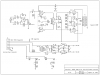
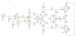
Alright, here's my updated schematic. Pretend those 7912 and 7812 regulators are actually 7818 and 7918. Also, is there a way to calculate how much current those op-amps will draw? If I go off of the spice model, I think that the circuit will draw about 7.5 mA per channel, but I'm wondering if there's a good way to calculate that without using LTSpice.
Someone asked what the .01 uF capacitors from the screen grids to ground are, and I put them there to kill parasitic oscillations.
By the way, I am using a 12 volt heater supply. The 6L6GC in this is actually a 1625 and the 6SN7 is actually a 12SN7, but that should have no effect on how it gets designed.
Thanks, that's exactly the kind of thing I was hoping to find. I'll check that out.
Someone asked what the .01 uF capacitors from the screen grids to ground are, and I put them there to kill parasitic oscillations.
By the way, I am using a 12 volt heater supply. The 6L6GC in this is actually a 1625 and the 6SN7 is actually a 12SN7, but that should have no effect on how it gets designed.
I can't recommend Douglas Self's book enough if you are a beginner with op amps and audio.
Thanks, that's exactly the kind of thing I was hoping to find. I'll check that out.
Attachments
...is there a way to calculate how much current those op-amps will draw?....
I wonder if it is on the datasheet?
Hopefully 100K... since I have a bunch of 100K linear pots...
6L6GC with 300 V at screen requires some -25 V to -30 V grid bias. Have you calculated what the raw minus supply should be with the present schematic and 100 k bias balance pot. I quickly calculated that at least some -200 V is reguired, because of so many voltage dividers.
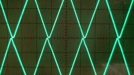
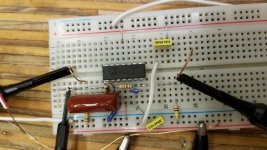
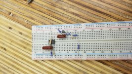
Over the weekend I managed to find time amidst the ocean of Calculus work to breadboard the phase splitter circuit, and it seems to perform pretty well.
Those who pointed out the possible latency issues were spot on. I estimate that to be about .15 microseconds. That's about a 400 kHz triangle wave I'm feeding into the circuit there to make it visible. 150 nanoseconds is pretty minimal, and if I suspect this won't be audible. If I were designing this circuit to work at 100+ kHz, I'd be concerned, but unless this causes stability issues with the GNFB circuit, I'm probably not going to worry about it.
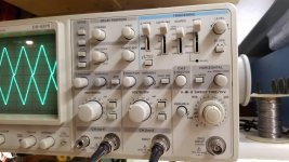
Also, ignore the quality of the triangle wave. My function generator is a Wavetek Model 130, and it was made the same year we put a man on the moon. It could benefit from a bit of TLC.
I ended up changing the value of C12 and R28 to adjust my low-end rolloff. Should have double checked my calculations the first time, since I had a noticeable roll off at like 30 hz. I don't have the new schematic in front of me at the moment, but I want to say those got changed to 100k and .470 uF, respectively.
Progress is being made. Also, due to me not wanting to cut a bunch of large holes in a 1/4" Aluminum chassis, along with the annoying limitations of the 6 pin connector, all this multiple chassis BS has been ditched. Those chassis will be put to use for something else where they are better suited. I can now do a real power supply for the op amp. Thinking of maybe using Purpleheart for the sides of the chassis and maybe even dovetailing it (we'll see how ambitious I am... it's not my favorite wood to work with, but it sure is pretty).
Those who pointed out the possible latency issues were spot on. I estimate that to be about .15 microseconds. That's about a 400 kHz triangle wave I'm feeding into the circuit there to make it visible. 150 nanoseconds is pretty minimal, and if I suspect this won't be audible. If I were designing this circuit to work at 100+ kHz, I'd be concerned, but unless this causes stability issues with the GNFB circuit, I'm probably not going to worry about it.
Also, ignore the quality of the triangle wave. My function generator is a Wavetek Model 130, and it was made the same year we put a man on the moon. It could benefit from a bit of TLC.
I ended up changing the value of C12 and R28 to adjust my low-end rolloff. Should have double checked my calculations the first time, since I had a noticeable roll off at like 30 hz. I don't have the new schematic in front of me at the moment, but I want to say those got changed to 100k and .470 uF, respectively.
Progress is being made. Also, due to me not wanting to cut a bunch of large holes in a 1/4" Aluminum chassis, along with the annoying limitations of the 6 pin connector, all this multiple chassis BS has been ditched. Those chassis will be put to use for something else where they are better suited. I can now do a real power supply for the op amp. Thinking of maybe using Purpleheart for the sides of the chassis and maybe even dovetailing it (we'll see how ambitious I am... it's not my favorite wood to work with, but it sure is pretty).
Attachments
The 6Y6 project I worked on with Jeff Yourison would not have been possible, without the MOSFET "concertina" phase splitter. No triode I am aware of can swing as close to the B+ rail as a MOSFET.
But what can you expect from a low input impedance and low gain driver out to a needy output tube? If you had used a common 6GH8A driver stage with the triode cathodyne you could drive the 6Y6 easily.
New Driver
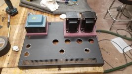
Well I've made some progress on my chassis (Steel chassis = a pain). Also learned that step drills and powder coating don't go so well together, even when you drill from the backside. Definitely should have put down some tape to protect the finish. Looks like I've got some painting ahead of me. As is typical for me, I'm a cheapskate who refuses to buy a chassis, so this is a reused 1u Chassis from some old lighting control equipment. I had to be creative to deal with some less than conveniently positioned ventilation slots. The PT also needs more clearance underneath than a 1u chassis can provide, so it needed a spacer. In one of my less bright moments, I decided that I should use purpleheart to make these parts on the grounds that it will "look great". Lesson learned, this wood sucks to work with. I've only ever done small details on other projects with it (inlays and the like) so I didn't realize that 1) It's almost as hard as aluminum, and 2) I'm allergic to it. First exotic hardwood I've come across that's really a problem for me in that regard. At least it looks interesting. I'm just glad I didn't try to make the whole chassis out of it though, it's incredibly brittle and prone to tearout. I ended up putting the parts on the mill and milling out the transformer cut-out with a 1/4" solid carbide endmill (razor sharp). That worked okay so long as I ran it at 1400 RPM (max speed of my mill), but any less than that and it would tear out.
As I've been working on this, I've been mulling over how I can improve my phase splitter design. The original design isn't really 180 degrees out of phase. It's close, and using a reasonably fast op-amp like the AD713 does help with the issue, but it will never be perfect, and I'm a little concerned that this will cause instability with global negative feedback applied.
This is what I came up with. It uses an OPA604 (probably a better op-amp than the AD713) for a voltage amplifier (Only a tiny bit- just a gain of 2 in that stage), a JFET for the phase splitter, and a 6SN7 for the driver. Yes, MOSFETs are better from that, but the FETs don't make for a very pretty chassis layout.
Testing of the circuit highlighted a few issues that needed to be resolved. Most notably was that without the 47 pF cap in parallel with the feedback the resistor, the OPA604 would break into oscillation up in the megahertz region. Second, production tolerances on the J112 JFETs necessitated a 5k pot for adjusting the bias.
I'd love to hear thoughts on this design. I used the J112 just because I had it in stock and the J112 spice model I found seemed to behave well. That said, I don't know if there are better JFETs for audio usage. I originally ordered the J112s to fix something that used them as a switch, so they may not be particularly linear.
Please note that the voltage rails in this schematic are WRONG. I'm still learning how to use KiCAD (just started using it the other day), and haven't yet figured out how to fix that. Beyond that I like it. Unlike ExpressSCH, it actually has keyboard shortcuts- something I'm very used to from using other software like Adobe Premiere and Solidworks.
Attachments
About time for an update.
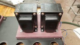
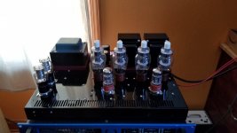
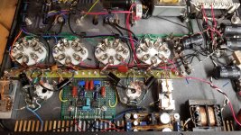
Firstly, the thing is built and it turned out reasonably well. The 0D3 tubes, as impractical as they may be, look pretty sweet.
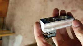
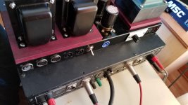
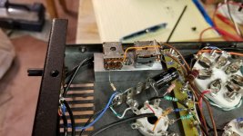
I made some adapter blocks to recess the bias controls so they can't accidentally get bumped. I'm using a 2-gang 100K linear pot with both sections wired in parallel to get a 50K pot. The only reason I did it this way was due to the large number of these pots on hand. They have an awkward 4mm shaft diameter as well. I am using a 6-pin XLR connector for bias measurement simply because it was convenient. If anyone has a better solution for this, I'd love to hear about it.
The first phase inverter design worked reasonably well with one problem: There isn't a real convenient place to connect negative feedback.
To rectify this issue, I switched to the second design with the JFET and the OPA604. The global negative feedback loop is connected directly to the OPA604 inverting input.
There is just one tiny problem with this, however. Stability. In this case, however, it's not an OPT issue. The Hammond 1650P output transformers seem to have relatively good HF performance. The problem is low-frequency instability, which I was able to trace back to phase shift caused by C1. I was able to get it stable by putting a small capacitor in series with the 56K feedback resistor. I didn't do the calculation, however this translates to somewhere in the neighborhood of 10dB of negative feedback, possibly a little more.
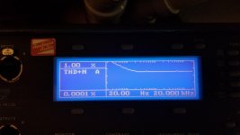
This, however, caused the frequency response shown in the attached image- not ideal. I replaced C1 with a 22uF Electrolytic capacitor, which improved the low frequency phase shift considerably. That said, LF instability is still an issue. The capacitor in series with the feedback resistor was changed to a .15 uF. I still have a noticeable rise in frequency response at 30 Hz, and while the amp doesn't break into oscillation at 5Hz, I do notice that when the volume is adjusted quickly there is a small amount of low-frequency oscillation that dies out after a second or two- something that obviously needs to be addressed.
With that said, THD is quite good. The amp averaged about 0.2%-0.5% THD throughout the audio spectrum, though it was significantly higher in the bass area due to the lack of negative feedback.
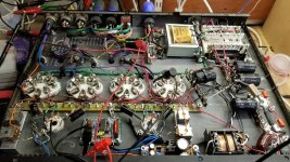
Noise is a little unimpressive. I measured the noise floor at about -65 dB, and I would like to get that down a bit lower. -75 or -80 would be nice. Some of this is likely a slightly imperfect grounding scheme that needs tweaking. When I first tested it, I was a bit horrified to see that the noise floor was about -25dB . I traced this back to the small transformer used to power the input board. For whatever reason, no matter how I connected them, the transformer would ring like a bell with both primaries connected. Since I'm only pulling about 25% of its rated current, I decided to only use one of the two primaries.
Work on this has been slow as I'm only able to work on it on the weekend.
If anyone has ideas for getting the NFB circuit to work properly, I'm all ears.
H713
Firstly, the thing is built and it turned out reasonably well. The 0D3 tubes, as impractical as they may be, look pretty sweet.
I made some adapter blocks to recess the bias controls so they can't accidentally get bumped. I'm using a 2-gang 100K linear pot with both sections wired in parallel to get a 50K pot. The only reason I did it this way was due to the large number of these pots on hand. They have an awkward 4mm shaft diameter as well. I am using a 6-pin XLR connector for bias measurement simply because it was convenient. If anyone has a better solution for this, I'd love to hear about it.
The first phase inverter design worked reasonably well with one problem: There isn't a real convenient place to connect negative feedback.
To rectify this issue, I switched to the second design with the JFET and the OPA604. The global negative feedback loop is connected directly to the OPA604 inverting input.
There is just one tiny problem with this, however. Stability. In this case, however, it's not an OPT issue. The Hammond 1650P output transformers seem to have relatively good HF performance. The problem is low-frequency instability, which I was able to trace back to phase shift caused by C1. I was able to get it stable by putting a small capacitor in series with the 56K feedback resistor. I didn't do the calculation, however this translates to somewhere in the neighborhood of 10dB of negative feedback, possibly a little more.
This, however, caused the frequency response shown in the attached image- not ideal. I replaced C1 with a 22uF Electrolytic capacitor, which improved the low frequency phase shift considerably. That said, LF instability is still an issue. The capacitor in series with the feedback resistor was changed to a .15 uF. I still have a noticeable rise in frequency response at 30 Hz, and while the amp doesn't break into oscillation at 5Hz, I do notice that when the volume is adjusted quickly there is a small amount of low-frequency oscillation that dies out after a second or two- something that obviously needs to be addressed.
With that said, THD is quite good. The amp averaged about 0.2%-0.5% THD throughout the audio spectrum, though it was significantly higher in the bass area due to the lack of negative feedback.
Noise is a little unimpressive. I measured the noise floor at about -65 dB, and I would like to get that down a bit lower. -75 or -80 would be nice. Some of this is likely a slightly imperfect grounding scheme that needs tweaking. When I first tested it, I was a bit horrified to see that the noise floor was about -25dB
. I traced this back to the small transformer used to power the input board. For whatever reason, no matter how I connected them, the transformer would ring like a bell with both primaries connected. Since I'm only pulling about 25% of its rated current, I decided to only use one of the two primaries.Work on this has been slow as I'm only able to work on it on the weekend.
If anyone has ideas for getting the NFB circuit to work properly, I'm all ears.
H713
Attachments
if you have your feedback on the positive input pin of the op amp (post #25), the amount of feedback changes with volume. it should go on the negative (inverting ) input as it will not vary with volume. the phase of the output will need to change, easiest way is to ground the plus speaker output as opposed to the minus and connect the feedback to the opposite pin.
Yes, that is an issue with that drawing. I didn't ultimately do nearly as much testing with the first board as with the second one (with the JFET). I may revisit it in the future. As it stands, I'm fairly certain I need to take a look at the coupling capacitor values. My understanding is that when calculating them I need to "stagger" the RC time constants, though I'm still learning how to do this. I believe this is the reason for my low frequency instability. I KNOW I have excessive phase shift at low frequencies, and my suspicion is that coupling capacitors in several areas is the reason for this, particularly those on the driver board.
Yes, three coupling capacitors is asking for trouble with LF instability. Other than staggering the time constants (which might not be enough), maybe you could look at differential feedback (from each end of the secondary) to the cathodes of the ecc88. You would need a small value resistor in each cathode leg before the common resistor to ground. This is assuming distortion from the voltage amplifier and phase splitter is negligable.
Alternatively you could put a shelving network (RC in parallel) in series with C1 to reduce the open loop gain below 20 Hz (Patrick Turner mentions this a few times on his site). C1 could be increased to say 0.47 uF, with shelving network values of 0.022 uF and 3.3M, and reduce R4 to 470k. In simulation this works better than just having a low value for C1.
Alternatively you could put a shelving network (RC in parallel) in series with C1 to reduce the open loop gain below 20 Hz (Patrick Turner mentions this a few times on his site). C1 could be increased to say 0.47 uF, with shelving network values of 0.022 uF and 3.3M, and reduce R4 to 470k. In simulation this works better than just having a low value for C1.
- Status
- This old topic is closed. If you want to reopen this topic, contact a moderator using the "Report Post" button.
- Home
- Amplifiers
- Tubes / Valves
- 6L6GC PP amplifier with SS phase inverter