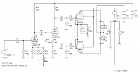
I've built myself a little EL95 push-pull amp. The schematic was copied from an old tube radio, don't remember which one though. After getting it to work without an excessive amount of hum (which was induced by the mains transformer) I'm now trying to figure out where the remaining hum is coming from. Didn't get all too far just yet, but here's a first thing I stumbled upon.
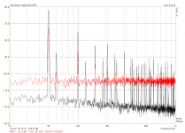
One amp channel is hooked up to the soundcard output, the transformer output is terminated with a beefy 8 ohm dummy load and connected to the soundcard input, to make some measurements. The black trace shows the output noise of the amplifier, with no signal on the input (but with the soundcard connected of course). There's plenty of 50Hz mains hum and harmonics, even 60Hz, wherever that is coming from (we are on 50Hz here in Germany). That noise is still present when I disconnect the mains of the amplifier and the amplification slowly collapses. When I plug in the amplifier, the noise floor remains clean - the hum only starts to become visible after several seconds, when the tubes are properly heated up.
This tells me that the 50Hz noise must be picked up by the working input stage. I tried to reduce it by increasing negative feedback of the amplifier (or decreasing overall gain, if you like). For this I simply shorted out C2 in the schematic, which basically reduced the feedback network from 22k/2k2 to <2k2/2k2. The result is shown by the red trace. You can see that all the hum spikes are reduced in magnitude and most of them are drowned in the noise floor already, but look what has happened to the noise floor itself! Why did it rise by over 10dB?
Somebody enlighten me, please
Attachments
Is the noise present on a basic loopback test of the soundcard itself?
No, the loopback noise floor is even lower.
How are the heaters wired and grounded? AC with a resistor from each leg to ground is usually a good way to prevent hum.
Forgot to mention this. Since I had severe problems with the original mains transformer, I'm currently powering the amp with SMPS'. There's one set to 6.3VDC for the heaters and 6x 45VDC in series for the 270V.
Too much feedback can cause oscillation, which may show itself as extra noise.
That might actually be the cause. I'll hook it up to a scope and see if I can find some evidence.
Attachments
Shorting C2 basically puts R13 in parallel not only with R14, but also with R11.
You should see the voltage on the first triode decrease as a result of the increased current and resulting higher voltage drop across R10.
Teensy DC current going through the opt secondary as well: half the current through the first triode. Not enough to worry about it guess.
You should see the voltage on the first triode decrease as a result of the increased current and resulting higher voltage drop across R10.
Teensy DC current going through the opt secondary as well: half the current through the first triode. Not enough to worry about it guess.
You could also try running the amp without the feedback loop in place - just to see if the hum goes up or down, or, as DF96 suggests, there is oscillation.
I'll give that a try.
And yes - oscillation it is. A solid 400kHz, way out of range for a humble soundcard. I should have noticed that myself, since I basically crushed the feedback through the floor, but that's what you guys are there for
. Thanks!Shorting C2 basically puts R13 in parallel not only with R14, but also with R11.
You should see the voltage on the first triode decrease as a result of the increased current and resulting higher voltage drop across R10.
Teensy DC current going through the opt secondary as well: half the current through the first triode. Not enough to worry about it guess.
Sorry, but I don't understand what you want to say
EDIT: Opening up the feedback loop increases the noise and distortion. I'll have to carefully increase the feedback for a little reduction in noise and still avoid oscillations. Or skip the first stage altogether and let my preamp do all the work...
Last edited:
Sorry, but I don't understand what you want to say
Originally, the cathode is connected to ground through the 2k2 kathode resistor, but also through the 22k feedback resistor (in series with the 8ohm load and OPT secondary). So the DC operating point is set by a total 2k in the cathode (2k2 in parallel with 22k).
When you short C2, there is another DC path to ground, through R13 (2k2). This results in only 1,05k between cathode and ground.
Smaller cathode resistor: higher current.
Checking it however, the difference is small: you should go from 0,48mA to 0,62mA (calculated in TubeCAD).
A little more voltage drop across V10 (220k), so the anode voltage drops from 117V to 87V.
The main point is that you change more than just the NFB when shorting C2.
The ELL80 is feeding a resonant circuit. Resistors in series with C3 and C8 might be added for critical damping. R2 and R3 are too high, estimated -3dB at 200...300 Khz which adds to (unwanted) phase shift in the feednack loop. 1k usually is enough to prevent parasitic oscillation.
(...) The main point is that you change more than just the NFB when shorting C2.
Now that makes sense to me
. Thank you for being more thorough 
The ELL80 is feeding a resonant circuit. Resistors in series with C3 and C8 might be added for critical damping. R2 and R3 are too high, estimated -3dB at 200...300 Khz which adds to (unwanted) phase shift in the feednack loop. 1k usually is enough to prevent parasitic oscillation.
I'm not familiar enough with tube circuits to understand in detail what you wrote
. What can I expect to happen when I decrease R2 and R3 to 1k? Probably some more stability margin for increasing feedback? There's more what Lingwendil mentioned before, R7 and R8 could be made larger... Why?Now that makes sense to me
I'm not familiar enough with tube circuits to understand in detail what you wrote
With the value of 47k, R2 and R3 and control grid input capacitance plus miller effect, an unwanted low pass filter is created within the feedback loop. If the value is changed to 1 k, it won't have an effect on the circuit apart from preventing parasitic oscillation.
When increasing the value of R7 and R8 to 100k you probably would have to increase the value of R6 as well. Ideally, it should have a value such that over R7 and R8 is 1/3 of the supply voltage. That leaves 1/3 of the supply voltage over the tube.
- Status
- This old topic is closed. If you want to reopen this topic, contact a moderator using the "Report Post" button.
- Home
- Amplifiers
- Tubes / Valves
- EL95 push-pull, increasing NFB increases noise?