Hello all,
I've bought second hand integrated amp MingDa MC-34A. It sounds good, but it have way too much gain... I'm even below 9 o'clock on volume control in normal listening levels.
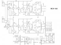
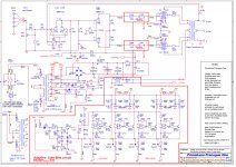
Can somebody please give me advice, how to properly lower gain in preamp stage? Schematics attached.
Just lower 12ax7 100k plate resistor to 47K? Or maybe even omit second 12ax7 stage completely?
Thank you in advance")
Kamil
I've bought second hand integrated amp MingDa MC-34A. It sounds good, but it have way too much gain... I'm even below 9 o'clock on volume control in normal listening levels.
Can somebody please give me advice, how to properly lower gain in preamp stage? Schematics attached.
Just lower 12ax7 100k plate resistor to 47K? Or maybe even omit second 12ax7 stage completely?
Thank you in advance
Kamil
Attachments
it have way too much gain... I'm even below 9 o'clock on volume
control in normal listening levels.
Don't change the circuit, you need all the stages.
Do you have test equipment? Lowering the NFB 100k resistor to 15k should do it,
but you will need to add compensation for stability to prevent oscillation.
Otherwise, you can just add a resistor from the volume control wiper to ground.
Choose the value so that the normal listening level is around halfway up.
Try starting with 5k.
Increasing feedback by a factor of 6 will be severely testing the quality of the OPT. However, if it is good enough you might be able to make it stable with some compensation.
That amp circuit shows two common shortcuts; why do commercial amps save a few pence on components yet expose the user to future problems?
1. There should be a coupling capacitor between the volume pot wiper and the first grid. This reduces pot noise and lengthens pot life.
2. There should be a safety resistor by each bias pot so when the wiper lifts off the track the output valve still gets bias and doesn't overheat.
Jon, the 'X7 voltage amplifier is inside a GNFB loop. So, inserting a 'U7 there will not work. The NFB resistor pair controls the closed loop gain, provided open loop gain is sufficient.
I suggest a simple solution. Insert low noise, metal film, 100 Kohm resistors into the lines connecting the source selector to the volume controls. 6 dB. of attenuation are obtained, which should be enough to tame the "hair trigger" condition.
I suggest a simple solution. Insert low noise, metal film, 100 Kohm resistors into the lines connecting the source selector to the volume controls. 6 dB. of attenuation are obtained, which should be enough to tame the "hair trigger" condition.
I'm even below 9 o'clock on volume control in normal listening levels.
Can somebody please give me advice, how to properly lower gain in preamp stage? Schematics attached.
Is your source signal much larger than the input sensitivity specification for the amp? If it is then you may not want to permenantly change the gain for all inputs. If you have high input signal from a DVD player, get a line attenuator for that one source.
Thank you very much for replies...
Rayma: No, unfortunatelly I don't have measuring equipment, only simple multimeter.
Eli: I can put resistor there, but this is not solution I'm looking for... painfully amplify DAC signal and than shunting it back down and then amplify again for no reason. This change is somewhat "virtual", only moves volume pot up...
20to20: My source is common CD player with <2Vpp. I would like to change behavior of whole amp. I have also Almarro 318b, which have proper gain for me, it is at 11 o'clock at normal listening levels.
DF96: Thank you for pointing me faults of design, I'll put coupling caps there. What value of safety resistor do you mean?
There is much to criticize on this amp. I think it was designed by dartboard. Implied input sensitivity of 62mV is FAR too high for most systems. The bias pot allows you to dial bias down to *zero*, which would be disastrous. DF96 makes good points.
If you are "stuck" with this amplifier, accept it and adapt it.
You can't trim the NFB much. Actually I am not sure it even has NFB. The first stage has 1K in cathode so gain is like 25; 2nd stage is SE long-tail so gain is like 8; gain of 200 to this point. The final stage has gain from one grid to 8r speaker of like 0.57. Gain from input to speaker is like 114. NFB network ratio is 100K:390r or 257. There is not enough gain to satisfy the NFB, nominally. So all the NFB can do is limit the rise at bass resonance and treble rise. It may be a fair guitar amp, where we *want* the speaker to be "loose", add tone to the sound.
The actual input sensitivity is like 0.16V. This was not an uncommon figure for older systems and their analog sources. However a straight DAC directly outputs up to 2V, and modern recordings fill that up all the way. You may have 10 times the gain you really want.
(BTW: we do not "painfully amplify DAC signal". It comes out of the digital bits already at high voltage, from 2.8V or 5V references. The post-DAC stages are typically unity-gain filters, not boosters.)
I have a raw guess that the 100K NFB resistor could be 22K without instability. That is *assuming* it is even wired correct phase; the other sloppy-bits suggest they had little idea what they were doing. (It may be 100K because anything less caused PFB and howled, and they didn't know why.)
Short of some major re-build, _I_ would just pad the input. The 100K volume pot is not so very high. We can just add a series resistor.
Attachments
PRR: Thank you for reply... I didn't thought that design is that bad
Actually, this is my second tube amp, meant to power my home cinema. My first thought was to make copy of Almarro 318b, but when I saw prices of good output transformers and other parts, I decided to not do it.
This Mingda was very warmly received in Polish hifipress, and they sold maybe thousands of them in Poland... I've also heard it couple of yeard ago on hifishow and sound was damn good for this price (new was about 1100USD).
So I'm not stuck with Mingda, but just to make it little bit better, adjust gain, etc. I've picked it at 300USD, which is not even half price of parts when I was considering DIY
DAC - Yes, I'm doing it painfully, because I have current output DAC, where I need to have proper and very good I/V convertor
For a bias safety resistor use something like 10 or 20 times the bias pot value. Connect from bias pot wiper to bias negative supply rail. You will then need to adjust bias.
Great, thank you. I'll do it
5751 vs 12ax7
The published sensitivity of the PimaLuna is 300mv and the Mingda is 200mv.
I have the version of this amplifier with the preamp output. I am not happy with the sound. I plan to put it on the bench and check/adjust the output tubes bias.
Can someone comment about replacing the 12ax7 with 5751 tube? If I did this would I need to adjust the feedback?
Steve
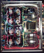
I opened up the Mingda MC34-A-2000 chassis.
The output tubes bias was off more than 15ma between tubes in each pair. That may be part of the reason I was unhappy with the sound. Only a few minutes of fiddling with the grid pots and each pair matched within 0.1ma at approximately 42ma.
I put it on the scope. A 300mv input produced 28 volts peak output on the 8 0hm tap to a load resistor at 30hz, 1khz, and 20khz. At 20hz the waveform began to distort badly at 15volts peak. The 100 watt load resistor measured 8.8 ohms so ~44 watts single channel driven.
I put a 100k ohm pot in parallel with one of the 100k ohm NFB resistors. I adjusted it while viewing the output on the scope. And then tested without load to see if it would oscillate. I settled on 22k ohm in parallel with the 100k ohm NFB resistor. I reran the power tests and got the same full power with an 800mv input level.
Next I subbed in a pair of 5751s for the 12AX7s. As expected sensitivity went down to 875mv for full output. Everything else seemed the same. Nothing about the sound was noticeably different out of the one cheap speaker I used for the test. I put the 12AX7s back in.
The only experience that I have with EL34 tubes is an 8 watt per channel SE amp that I run close to maximum tube dissipation. I don’t have a manual so I do not know how the manufacture intended this amp to be biased. This PP amp has 415 volts plate to cathode. The datasheet says 30ma per tube for this approximate voltage. 12 watts plate dissipation at idle seems low. I upped it to 16 watts. Is the typical 70% plate dissipation recommendation for cathode bias and for fixed bias it is lower?
Attachments
I put the 5751 tubes back into the amps gain stage.
I tested my AC line in and was getting ~120volts. I connected the amp to a variac and adjusted the AC line in to 116 volts which gave me 6.3 volts on the tube filaments and ~400 volts on the output tube plates.
I adjusted the grid pots until the output tubes operating point was at 50ma. I repeated previous tests and the results were same as before.
I connected to AC line in without the variac. Filament voltage went to 6.6 volts and output tubes plate voltage increased to 415 volts. Cathode current rose to 54+ma. I repeated previous tests and the results were same as before.
I closed it up. Connected it directly to my Jolida JD100 CD player with tube outputs. I listened to dozens of CDs from many different genres (piano, jazz, rock, classical, etc.). I listened to it for several hours. I liked everything I played through it.
I was planning on selling this amp after I completed the tune up but I have decided to keep it for my personal use.
Steve
...Is the typical 70% plate dissipation recommendation for cathode bias and for fixed bias it is lower?
"70% rule" has no basis in theory but tends to work OK for push-pull fixed-bias amps; unless they are very over-volted.
In single-ended the tube must suck ALL the power it can ever hope to put OUT, all the time. Economics dictate that you run at "100%" of rated dissipation to get all that you paid for.
Cathode biased push-pull amps will de-bias if the current changes with signal, so they too are usually run at 100%.
Of course economics must also include life. If you need a dog-sled to replace a tube above the Arctic Circle you may want a bigger tube worked at 60% Pdiss so you don't have to make that trip so often.
I said 70% recommendation (guideline) not rule.
There is a basis in theory but it may not be related to what you had in mind when you made that statement.
Idle Current Biasing - Why 70 percent?
Most of the push pull amps I use are cathode biased. I have little experience with grid bias and none with EL34s in a push pull amp.
The sine waves look excellent at all levels and I like the sound at 50ma cathode current and 400 volts plate to cathode in this amp. At 30ma the crossover distortion was beginning to show when I got near max power. Hence, why I ask the question.
I was hoping someone with experience with EL34 pp ul amps would share some opinions about operating points.
Steve
- Status
- This old topic is closed. If you want to reopen this topic, contact a moderator using the "Report Post" button.
- Home
- Amplifiers
- Tubes / Valves
- MingDa MC-34A - How to lower gain?