Hi Folks.
I bought a little DIY tube component a little while back that has a separate power supply chassis connected with an umbilical to a circuit chassis containing two 6922 tubes, two RCA inputs, and two RCA outputs. I wasn't sure what it was when I purchased it, but I figured it was either a phono preamp, or a buffer of some sort. I have drawn out the circuit and attached it for your consideration. The circuit drawing shows one channel, and excludes the heater wiring, the power supply, and the grounding of the internal shield of the 6922, all of which are present. The other channel is identical.
What is this device? What is its function and purpose? Are the in and out labeled correctly?
Thanks in advance for your responses.
Attachments
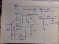
First redraw it vertically. Put pins 6, 7, 8 on the bottom and pins 1,2, 3 above it will become a classic u follower (mu follower). The input on pin 7 and output from pin 3, so yes incorrectly labelled.
Try this The Valve Wizard -Mu Follower
Alan
Try this The Valve Wizard -Mu Follower
Alan
Thanks for the replies. To recap, it’s a mu follower, the in and outs are cross labelled, and the voltage is on the low side for 6922. What is the purpose of a seperate component containing only a mu follower? I read the Valve Wizard article and, if I understand it correctly, it seems that it might be useful as a buffer between a high output impedance preamp, and a low input impedance amplifier. Is this correct? Also, would it provide gain as drawn? There is no potentiometer in the circuit as it is. Last question, would there be any DC on the output as drawn?
... A What is the purpose of a seperate component containing only a mu follower? B I read the Valve Wizard article and, if I understand it correctly, it seems that it might be useful as a buffer between a high output impedance preamp, and a low input impedance amplifier. Is this correct? C Also, would it provide gain as drawn? D There is no potentiometer in the circuit as it is. Last question, E would there be any DC on the output as drawn?
V e r y simply,
A- The benefits of a 'cathode follower' (low output impedance etc.) with the ability to amplify. A cathode follower has less than unity gain so is really a buffer.
B - Correct. Useful for several applications.
C - Yes, mu is just another name for 'amplification factor'. (You will find it in the valve / tube data.) So a mu follower has an approximate amplification or mu of the bottom valve, unless there is some negative feedback applied. (6922 mu = about 33.)
D - Correct. You could fit one in place of or in parallel with the 1.1 meg resistor.
E - No, there should not be on the output socket. The capacitor blocks the DC voltage from pin 3 and only allows AC (signal) voltages through. If you have DC on the socket, the cap is faulty (leaking) or just floating and needs another 100k ohm (ish) resistor at the output socket to 'hold it' ground. In fact if you are intending to try it as a pre amp fit one anyway.
Have you drawn a diagram of the power supply by the way? Or did you measure 170 volts not 70? Alan
A typical mu follower has output impedance much higher than a typical cathode follower, so may not be suitable for driving a low resistance load. Speaking very approximately, a CF has output impedance around 1/gm, a grounded cathode stage mu/gm, and a mu follower somewhere between the two - maybe as a rough estimate assume sqrt(mu)/gm?
Alan4411: I double checked, and the circuit is definitely operated at 70 Volts. I thought that this circuit might be have been intended as a buffer of some sort, and the reason that I asked about it is that I have a tube preamp (the 4S Universal from DIY Audio Projects) with an output impedance of 65K-78K. My Amp Camp Amp and my recently acquired Audio Zone Amp-1 both have an input impedance of around 10K Ohms, and don't work with the 4S Universal. One option presented by the designer of the 4S is to rework the circuit and add a cathode follower, and another tube, but seeing as this self contained 6922 mu-follower is at hand, perhaps I can avoid this modification and just use the mu-follower as a buffer that will lower the output impedance sufficiently for my two SS amps.
DF96: Using the formulas provided by yourself, and using mu of 33, and GM of 12000 for the 6922:
Cathode follower - 1/GM=1/12000=.000083 - 8.3 Ohms
Grounded cathode - mu/GM=33/12000=.00275 - 275 Ohms
Mu follower - square root of 33/12000=5.74/12000=.004783 - 47.8 Ohms
I'm not sure if I'm doing this correctly, but it seems that the mu follower should be fine as a buffer between the 4S Universal preamp and either one of the SS amps with 10K Ohm input impedance. Please do correct me if I'm wrong.
What would be the best way to use the circuit only as a low output impedance buffer with unity gain? I really don't need any more gain, and a volume pot is just one more thing in the signal path that I will need to fiddle with. Is it best to use feedback, or is there another way to do it? Any suggestions would be most appreciated.
What would be the best way to use the circuit only as a low output impedance buffer with unity gain? I really don't need any more gain, and a volume pot is just one more thing in the signal path that I will need to fiddle with. Is it best to use feedback, or is there another way to do it? Any suggestions would be most appreciated.
A simple (probably the best) way is to chop it in half and make it a cathode follower. (There are many more complicated variants, if you google ECC88/6922 Cathode Follower or look in Merlin's book.)
The problem you will have was pointed out by Eli back in post 3, you do not have enough B+ even for a single valve. So start with a look at your power supply and ways to get B+ higher.
Example here needs 90 volts and more would be better. Calculating 6922/E88CC/ECC88 cathode follower for 90V anode
Alan
I think you need to multiply all your results by 10.tizman said:DF96: Using the formulas provided by yourself, and using mu of 33, and GM of 12000 for the 6922:
Cathode follower - 1/GM=1/12000=.000083 - 8.3 Ohms
Grounded cathode - mu/GM=33/12000=.00275 - 275 Ohms
Mu follower - square root of 33/12000=5.74/12000=.004783 - 47.8 Ohms
Then you need to be aware that the circuit you show has cathode degeneration, which will lower gain and raise output impedance.
PS you also need to be aware that the valve is biased to a fairly low current so gain will be lower and impedance higher. I am going to hazard a wild guess that the output impedance of this circuit is somewhere in the region of 1-2k.
Last edited:
....using mu of 33, and GM of 12000...
The ~~13,000uMho quote for 6922 is for about 12mA at 100V.
Gm drops with current.
Your image in post #1 is probably working nearer 1.5mA and 25V/tube. Without actually thinking, I'd estimate Gm is nearer 4,000uMho.
Which IS 1/250 Ohms, and 250 Ohms is plenty low in most hi-fi interconnects.
If you want unity gain, abandon the stacked configuration. Simple cathode follower is sweet and simple. With proper cathode resistor and bias, and retaining the way-small 70V supply, it can swing 14V peak or 10V RMS. The THD at that level will be near 5%/30 or 0.2%. Hi-Fi runs 1V-2V, so THD will be 0.02%-0.04%, satisfactorily low.
Here's a CF on the same parts.
If you truly hope for "250 Ohm output impedance", a part-uFd cap won't do, you need larger. But super-low Zout is rarely essential in hi-fi. 1uFd (3k Ohms at 50Hz) is often fine, and not too expensive as a good Film cap. 250 Ohms down to 20Hz requires 33uFd, which is probably an Electrolytic. E-caps distort, but less if over-size, so up to 100uFd is also something to try.
If you truly hope for "250 Ohm output impedance", a part-uFd cap won't do, you need larger. But super-low Zout is rarely essential in hi-fi. 1uFd (3k Ohms at 50Hz) is often fine, and not too expensive as a good Film cap. 250 Ohms down to 20Hz requires 33uFd, which is probably an Electrolytic. E-caps distort, but less if over-size, so up to 100uFd is also something to try.
Attachments
Thanks for the schematic and explanation PRR. The original circuit was put together in a small wooden box, with a thin wooden top plate holding the two tube sockets. Cutting out another small top plate for one tube, and putting in the circuit as per your schematic is going to be very easy to do. Given the low voltage of the B+, a 150 Volt cap should be fine, and I have a bunch of film caps that I can use. Thanks again!
A look at the datasheet suggests gm around 6mA/V for 1-2mA at 20V - which is quite remarkable. Based on this (and assuming mu of 30) I now estimate output impedance around 800 ohms. However, it won't have much driving ability with such low quiescent current. There may be a problem with grid current so it needs a fairly low impedance source, and it can't handle more than 1V in without clipping. Difficult to imagine what the designer thought he was doing - maybe making a mild effects box?PRR said:Your image in post #1 is probably working nearer 1.5mA and 25V/tube. Without actually thinking, I'd estimate Gm is nearer 4,000uMho.
Difficult to imagine what the designer thought he was doing - maybe making a mild effects box?
Agreed.
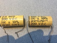
PRR: I went through my stash, and found a few pairs of film caps that I could use. 1uF at 630V, 2uF at 200V and 30uF at 300V. My inclination is to use the 2uF caps, as they are low voltage caps that I am less likely to have a need for in the usual tube circuits that I build. I attached a photo.
Eli and DF96: It may very well have been intended as an effects box, as the person I bought it from had equal amounts of tube based guitar and hi-fi stuff for sale. I'm not sure why he would have built it as a stereo circuit, with RCA inputs and outputs, if his intent was to use it for guitar though. What could the intended "effect" of the circuit be for hi-fi use?
Eli and DF96: It may very well have been intended as an effects box, as the person I bought it from had equal amounts of tube based guitar and hi-fi stuff for sale. I'm not sure why he would have built it as a stereo circuit, with RCA inputs and outputs, if his intent was to use it for guitar though. What could the intended "effect" of the circuit be for hi-fi use?
Attachments
I have a quick question about the original circuit. The 330 Ohm resistor from pin 8, and the 1.1 meg Ohm resistor after the .185 input cap are connected to the power supply ground wire, but the ground for the input and output RCA jacks are connected to each other and to pin 9, the internal shield, but not to anything else. It would appear that the signal ground and pin 9 are not grounded. Is there an internal ground in the valve through pin 9?
Pin 9 merely connects to the internal shield. It seems he must have relied on some external circuit (source or load) providing a connection between the RCA ground and PSU ground, presumably via the mains supply ground? Not a good idea.
It is difficult to think of what purpose a gain of around 30 could provide to almost any modern 'hi-fi' system. There are some people who buy a line stage and then find they have to buy an attenuator too. If it is a good line stage then all this setup does is add a little noise and distortion and will do little harm. If not, it adds more noise and distortion.
It is difficult to think of what purpose a gain of around 30 could provide to almost any modern 'hi-fi' system. There are some people who buy a line stage and then find they have to buy an attenuator too. If it is a good line stage then all this setup does is add a little noise and distortion and will do little harm. If not, it adds more noise and distortion.
- Status
- This old topic is closed. If you want to reopen this topic, contact a moderator using the "Report Post" button.
- Home
- Amplifiers
- Tubes / Valves
- What is this tube circuit?