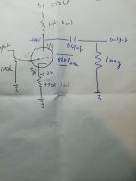
If you calculate with the measured voltages and the anode/cathode resistors the current through the used half of the 5687 is approx 16mA.
Nothing wrong with this for the 5687, the tube is just conducting more than in the schematic.
Note, the heater voltage should have a ground reference, not floating as is now.
Nothing wrong with this for the 5687, the tube is just conducting more than in the schematic.
Note, the heater voltage should have a ground reference, not floating as is now.
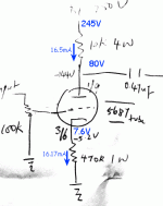
I have 245 v dc at B+. But only 80v at pin 1 of the tube.
I have 7.6 v at pin 3.
adjust the cathode resistor so that you get 120 to 125 or half of the B+..
be mindful of the plate voltage x plate current always...a fraction of the plate dissipation ratings ensures long life of the tube...
common cathodes can be designed for maximum gain or maximum plate swing, low plate voltage means high gain, while high plate voltage means more output swing, so the 1/2 B+ plate is a happy compromise i would say..
You shouldn't be drawing 16mA Ip with -7.6V bias. Something is causing that. Is the volume pot connected? Are there any DC on the input? If not could be gassy tube?
Volume potentiometer not connected
> Volume potentiometer not connected
I was about to say: What is the grid voltage?
The noted numbers do not plot as 5687 (assuming grid is ground-referenced).
If the grid is floating, well, almost anything can happen. Usual case IS the grid floats a few volts positive of circuit ground, until plate voltage falls enough to quiet the electron storm.
Attachments
Volume potentiometer not connected
KP,
Please try to connect a volume pot and re-check the measurement again. A floating grid might be a concern.
KP,
Please try to connect a volume pot and re-check the measurement again. A floating grid might be a concern.
VT4C and PRR ,
thank you for the good advice.
This is another diyer"s toy and I am hoping to learn something also.
regards
Last edited:
kp.
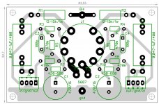
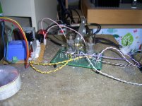
here is my little testboard, with options, for my test.
R3/4 - grid stopper not used
R5/6 - in place + C3/4- other/better experts knowing better if it makes sense")
R1/2 - 15k/2W
R7/10 - current 530 Ohm 430+100- in series for replacing other values
cathode bypass cap not used, but tested with/without
R8/9 - not used here, also not used output cap
I have tested this to drive M. Rothacher MoFo- unity gain Amp.
Around 300V on plate, behind 15k i not match the middle point ~ 120V.
But in difference on cathode stays ~ 4V in that resistor values.
Don't know if it helps for your needs.
here is my little testboard, with options, for my test.
R3/4 - grid stopper not used
R5/6 - in place + C3/4- other/better experts knowing better if it makes sense
R1/2 - 15k/2W
R7/10 - current 530 Ohm 430+100- in series for replacing other values
cathode bypass cap not used, but tested with/without
R8/9 - not used here, also not used output cap
I have tested this to drive M. Rothacher MoFo- unity gain Amp.
Around 300V on plate, behind 15k i not match the middle point ~ 120V.
But in difference on cathode stays ~ 4V in that resistor values.
Don't know if it helps for your needs.
Attachments
Thanks. Will implement these changes and report back. Will the tube work with a 80v dc at the anode? This pre will drive a Dynaco Vt 70. Source is cd player?
The CD player should have enough level (most do) to drive the Dynaco without a line stage. You can mount several volume controls in a box and make up the short cable needed to go from the RCA outs on the CD player to feed the volume control pot and then output from the volume control pot to the Dynaco input RCA jacks.
kp.
here is my little testboard, with options, for my test.
R3/4 - grid stopper not used
R5/6 - in place + C3/4- other/better experts knowing better if it makes sense
R1/2 - 15k/2W
R7/10 - current 530 Ohm 430+100- in series for replacing other values
cathode bypass cap not used, but tested with/without
R8/9 - not used here, also not used output cap
I have tested this to drive M. Rothacher MoFo- unity gain Amp.
Around 300V on plate, behind 15k i not match the middle point ~ 120V.
But in difference on cathode stays ~ 4V in that resistor values.
Don't know if it helps for your needs.
thank you for your suggestion.Very informative for tube newbie.
MOFO is next in line for build and does this pre drive it well ?
Do you like the sound ?
play with the cathode resistor instead, you can use a variable ppot to do that, then once you get to 1/2 b+, replace that with a fixed resistor to the nearest standard value...
going from 10k to 11.5k does nothing for you, but the cathode resistor gets you where you want your plate to be...
my quick and dirty calculation, with a b+ of 250 volts and 10k or 11.5k load resistor, a 500 ohm cathode resistor should give you a 120 volt plate...
going from 10k to 11.5k does nothing for you, but the cathode resistor gets you where you want your plate to be...
my quick and dirty calculation, with a b+ of 250 volts and 10k or 11.5k load resistor, a 500 ohm cathode resistor should give you a 120 volt plate...
5687 for MoFo go
affectations) tonality with dark backround.
There are more factors to influence the sound- a way to try, the much better, experienced experts knowing better details.
The cousin 6N6P-(I/EV) in mu follower circuit also sounds good to me.
My strongest is pentode 6P9- this is a little power animal there.
Don't take a critical look to long twisted wire- it is for testing.
For my, 2cent, opinion MoFo likes more gain producing tube, but the 5687 has solid (nonMOFO is next in line for build and does this pre drive it well ?
Do you like the sound ?
affectations) tonality with dark backround.
There are more factors to influence the sound- a way to try, the much better, experienced experts knowing better details.
The cousin 6N6P-(I/EV) in mu follower circuit also sounds good to me.
My strongest is pentode 6P9- this is a little power animal there.
Don't take a critical look to long twisted wire- it is for testing.
Attachments
- Status
- This old topic is closed. If you want to reopen this topic, contact a moderator using the "Report Post" button.
- Home
- Amplifiers
- Tubes / Valves
- Simple 5687 pre from diy paradise