After I wrote my previous notes about Yaquin MC-100B amplifier (see Yaqin MC-100B - not as powerful as advertised, but still a good value. ), I thought that I will continue to modify it. But somehow I was satisfied with its sound and being busy with other things I just used it along with my solid state gear. I fired it up when I had a mood to listen old music from old vinyl disks. But then I decided that it is time to upgrade speakers and found pair of reasonably priced B&W 802D in just one hour drive from my home. I couldn't miss this opportunity and sure enough - pair of only 4 years old speakers were now in my listening room. But together came a disappointment – tubes couldn't compete with transistors in driving new speakers. Yaquin didn't bring anything that my Yamaha MX-1000 didn't do in midrange and treble, but couldn't really control low bass – it was diffused and boomy. So Yaquin had to go and soon left my house in the hands of another audiophile. To keep price balance between amplifier and speakers, I also purchased Bryston 4B-SST. It did even better job than Yamaha to control low bass, but I am almost sure it gave up some air in treble. But anyway, Bryston became my primary amplifier and still is - up to present day.
But this was not the end of my endeavor to play with tubes. But now I wanted to go radically different – try what some consider quintessential in sound – SET amplification. Yes, I know that 802D are not the best speakers for that, but SET amplifier brings completely new approach to making sound and in that regard it was expected to be much more different comparing with Bryston which kept speakers in iron fist.
Of cause I understood nature of my new speakers – they are not very efficient, and though my listening room is rather small (12'x13'), they still needed considerable power to produce loud enough sound without clipping amplifier. So anything with famous 300B was out of question – I had to hit higher. Most popular tube, when one needs more that 5W from SET, is 845. And again by a good chance I found a Craigslist's ad from someone selling 845 based amplifier in the nearby village. Price was right and I didn't hesitate to get it. That was a Chinese made (what isn't made in China now) stereo amplifier from little known brand “Mr. Liang Audio”. It was made few years ago (looking forward - likely in 2008 based on components manufacturing date), but according to owner was not used much. Later doing research on that brand, I found that it changed name to ARTI (Single Ended 300B - 845 tube amplifier for sale | Audio Renaissance Technical Institute|Wuhan| P.R.C). Some people mentioned that this is a house brand of Yquin owner, under which he sells experimental products. I couldn't verify that claim.
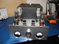
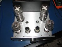
Amplifier is very well built – stainless steel chassis, thick aluminum front panel, potted output transformers, two power transformers (one supplies plate voltage to 845 tubes, the other - everything else), well made steel cages covering power transformers and tubes. From what I could find on ARTI web site – I got a second generation of Mr. Liang 845 amplifier. First one had different type of driver tubes and third (last one) had power transformers also potted. This is a very heavy amplifier – probably at the limit of a single person capable to move it around. Along with amplifier I got a set of spare tubes for input stage 6J4 (Chinese made pair and few old stock 6AC7), and spare pair of 300B driver tubes. Here you probably see what tube set is used in this amplifier – low signal penthode input, 300B driver and 845B transmission triode in output stage. It is advertised as integrated amplifier – has two selectable inputs and volume pot. But for my purposes I was going to use it as power amplifier working along with semi-vintage Yamaha C-2x as preamp.
I connected amplifier to my preamp and speakers and tried to listen it as is. I was disappointed – dark muddy sound with clear distortion when I tried to push it. It was advertised to produce 25W, but it was clear for me that this is too optimistic. Even at lower power levels there were too much distortions. But what the heck – I bought it like a kit for DIY exercise and I saw a lot of work ahead.
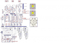
First I found what was known as schematic of this amplifier.
See Pic.1
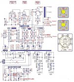
As you can see it is indeed uses 6J4 penthode doing all voltage amplification, directly coupled 300B in cathode follower circuit as driver, and finally 845 with fixed bias in output stage. All power supply is solid state, but with chokes in filters and regulated filament supply for 300B. 845 filament supply is not regulated, but still uses solid state rectifiers, as do plate and bias supplies. I should say that hum level from this amplifier was very low, so circuit is good in that regard. There is no either global or local feedback anywhere in the circuit, so in keeping distortions in check designers relied only on characteristics of tubes. And if 845 and 300B are relatively linear tubes, this cannot be said about 6J4 considering very high plate voltage swings needed to drive 845. So it was clear that the main problem if front stage circuit.
I opened amplifier and found that some components differ from what is shown in diagram above:
R101 was 390 ohm
C101 was 1000 uF Black Gate and clearly was someones custom job to install it
RF3 and RF4 were 38 ohms
R106 – 6.6 K
C103 though had same capacitance was clearly installed by someone after this unit left factory. These were M Cap silver and oil type.
I checked power supply and found very low ripple in both driver stage and output stage B+. Input stage supply was 440 volts and output stage got 1100 volts (which is on a higher side comparing with other 845 based amplifiers) when tubes were removed. Under normal operation conditions I saw 430 and 980 volts accordingly. Bias for output tubes at 95 mA current was about -120V.
I have circuit simulation software and decided to do research on computer first before making any changes in real circuit. I found SPICE models for 6AC7 and 845 tubes (300B was already in supplied library) and entered amplifier circuit as I found it. I used my new Mastech MS5308 LCR meter to measure main parameters of output transformer. I ran DC simulation and compared results (voltages and currents in different parts of circuit) with what I measured in real life. They were very close, so simulation models were close enough to work with them.
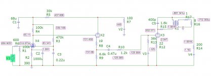
But it was immediately clear WHY amplifier sounded so poorly – the main problem was input voltage amplifier stage. Look how low plate voltage is – just 65 volts. And this is when you need at least 250 V peak to peak signal to drive 845 tube to the limit.
See Pic. 2
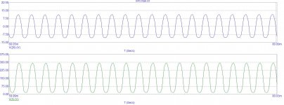
Thus small signal tube clipped well before driver and output tubes were used to their full potential. And this is understandable – penthode circuit with resistive load could not even in theory provide large voltage swing (considering loss in driver you need about 300 V peak to peak) and keep distortion low. Look at results of simulation – do you really like that “sine” waveform?
See Pic. 3
This amplifier had reasonable THD (below 1%) only well below 1 Watt. That was a reason WHY it sounded so dirty.
To be continued....
But this was not the end of my endeavor to play with tubes. But now I wanted to go radically different – try what some consider quintessential in sound – SET amplification. Yes, I know that 802D are not the best speakers for that, but SET amplifier brings completely new approach to making sound and in that regard it was expected to be much more different comparing with Bryston which kept speakers in iron fist.
Of cause I understood nature of my new speakers – they are not very efficient, and though my listening room is rather small (12'x13'), they still needed considerable power to produce loud enough sound without clipping amplifier. So anything with famous 300B was out of question – I had to hit higher. Most popular tube, when one needs more that 5W from SET, is 845. And again by a good chance I found a Craigslist's ad from someone selling 845 based amplifier in the nearby village. Price was right and I didn't hesitate to get it. That was a Chinese made (what isn't made in China now) stereo amplifier from little known brand “Mr. Liang Audio”. It was made few years ago (looking forward - likely in 2008 based on components manufacturing date), but according to owner was not used much. Later doing research on that brand, I found that it changed name to ARTI (Single Ended 300B - 845 tube amplifier for sale | Audio Renaissance Technical Institute|Wuhan| P.R.C). Some people mentioned that this is a house brand of Yquin owner, under which he sells experimental products. I couldn't verify that claim.
Amplifier is very well built – stainless steel chassis, thick aluminum front panel, potted output transformers, two power transformers (one supplies plate voltage to 845 tubes, the other - everything else), well made steel cages covering power transformers and tubes. From what I could find on ARTI web site – I got a second generation of Mr. Liang 845 amplifier. First one had different type of driver tubes and third (last one) had power transformers also potted. This is a very heavy amplifier – probably at the limit of a single person capable to move it around. Along with amplifier I got a set of spare tubes for input stage 6J4 (Chinese made pair and few old stock 6AC7), and spare pair of 300B driver tubes. Here you probably see what tube set is used in this amplifier – low signal penthode input, 300B driver and 845B transmission triode in output stage. It is advertised as integrated amplifier – has two selectable inputs and volume pot. But for my purposes I was going to use it as power amplifier working along with semi-vintage Yamaha C-2x as preamp.
I connected amplifier to my preamp and speakers and tried to listen it as is. I was disappointed – dark muddy sound with clear distortion when I tried to push it. It was advertised to produce 25W, but it was clear for me that this is too optimistic. Even at lower power levels there were too much distortions. But what the heck – I bought it like a kit for DIY exercise and I saw a lot of work ahead.
First I found what was known as schematic of this amplifier.
See Pic.1
As you can see it is indeed uses 6J4 penthode doing all voltage amplification, directly coupled 300B in cathode follower circuit as driver, and finally 845 with fixed bias in output stage. All power supply is solid state, but with chokes in filters and regulated filament supply for 300B. 845 filament supply is not regulated, but still uses solid state rectifiers, as do plate and bias supplies. I should say that hum level from this amplifier was very low, so circuit is good in that regard. There is no either global or local feedback anywhere in the circuit, so in keeping distortions in check designers relied only on characteristics of tubes. And if 845 and 300B are relatively linear tubes, this cannot be said about 6J4 considering very high plate voltage swings needed to drive 845. So it was clear that the main problem if front stage circuit.
I opened amplifier and found that some components differ from what is shown in diagram above:
R101 was 390 ohm
C101 was 1000 uF Black Gate and clearly was someones custom job to install it
RF3 and RF4 were 38 ohms
R106 – 6.6 K
C103 though had same capacitance was clearly installed by someone after this unit left factory. These were M Cap silver and oil type.
I checked power supply and found very low ripple in both driver stage and output stage B+. Input stage supply was 440 volts and output stage got 1100 volts (which is on a higher side comparing with other 845 based amplifiers) when tubes were removed. Under normal operation conditions I saw 430 and 980 volts accordingly. Bias for output tubes at 95 mA current was about -120V.
I have circuit simulation software and decided to do research on computer first before making any changes in real circuit. I found SPICE models for 6AC7 and 845 tubes (300B was already in supplied library) and entered amplifier circuit as I found it. I used my new Mastech MS5308 LCR meter to measure main parameters of output transformer. I ran DC simulation and compared results (voltages and currents in different parts of circuit) with what I measured in real life. They were very close, so simulation models were close enough to work with them.
But it was immediately clear WHY amplifier sounded so poorly – the main problem was input voltage amplifier stage. Look how low plate voltage is – just 65 volts. And this is when you need at least 250 V peak to peak signal to drive 845 tube to the limit.
See Pic. 2
Thus small signal tube clipped well before driver and output tubes were used to their full potential. And this is understandable – penthode circuit with resistive load could not even in theory provide large voltage swing (considering loss in driver you need about 300 V peak to peak) and keep distortion low. Look at results of simulation – do you really like that “sine” waveform?
See Pic. 3
This amplifier had reasonable THD (below 1%) only well below 1 Watt. That was a reason WHY it sounded so dirty.
To be continued....
Attachments
Last edited:
Here is a part TWO of report on my attempt to make Mr. Liang 845 amplifier sound better.
So now was a challenge – what to do with it. I could completely re-do the whole circuit, but that would require removal and replacement of PCB that contained all components (power supply had a second board, which I didn't even wanted to touch), or go with a limited change of circuit keeping most components in place. I decided to go a second way – the same like I did with Yaquin. But here more needed to be done – not just components with different parameters, but circuit itself had to be changed.
So now I needed to decide what type circuit needs to be used. He goal is to have very large voltage swing and low distortion. There is no way I could do it keeping resistive load. There are two methods to have circuit more efficient in using plate voltage – either load tube with transformer (or choke) or use CCS circuit. Considering that I had to work with existing power supply, and didn't want to add more tubes (which would require PCB replacement I wanted to avoid), I decided to go with with solid state CCS. Luckily enough not long before I read about a new components made by IXYS – three pin device that behaves like depletion type Mosfet and specifically designed to work as CCS in circuits with up to 900 volts. They need less than 10 volts to enter into saturation, so there will be little loss of B+ voltage if I could use them. I decided give them a try and ordered few pieces from Mouser. These devices cost only few dollars so I had little to loose. Then I had to decide what to do with tube. Penthode circuit had to go – the only way to get low enough distortion was to use triode. I could try something like 6SL7, which could be a very good choice, but that would require major alteration of circuit board. Here again I decided to try easiest path and use the same 6J4 tube, but in triode connection. Going that path I would trade a little of amplification, but will need to do much less actual work modifying a board.
When CCS devices arrived few days later, I built a breadboard circuit with 6J4 tube in triode connection and CCS as plate load. I could only power it up to 300 volts (all I can squeeze from my bench power supply), but even then I got reasonable amplification and 250 volts swing of output signal. So I proved a concept and next started designing new circuit around it. Most circuit design was done using computer simulation, and then only final adjustment done in real circuit. That saved me from making major mistakes (though I still made one, and describe it later). Hardest thing was to find a SPICE model for 6AC7 tube. I actually found two different ones, but only one of them provided results closer to what I saw in breadboard.
See Pic. 4
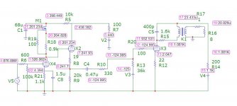
Key changes (besides rework of input stage) was increase of R9 so that idle current through driver tube is about 10 mA, and reduction of R5 to increase available B+ for first stage, and thus possible peak to peak amplitude of output signal. CCS (M1) model was taken from IXYS application guide – they use standard model of depletion mode Mosfet and supply parameters for their device to be used in simulation. In the circuit R18 defines the current through CCS. R19 prevents possible high frequency oscillation. R21 is a self bias resistor, it needs to be adjusted for every specific current set in CCS – this is the only in circuit adjustment that needs to be done. I used adjustable pots for both R18 and R21 because adjustment is needed for specific units of IXYS device and tube. C8 moves up roll off in treble compensating influence of input capacitance of 300B driver tube, which is significant comparing with dynamic impedance of CCS. I reduced current through 300B tube because I wanted to keep it reasonably low to avoid saturation of choke that filters B+, if it was rated to 25 mA (as mentioned on original diagram), I would have 28 mA passing through it (10+10+4+4), and keeping 20 mA would exceed specification almost two times (I do not know what designers thought when they chose components) and I didn't want to replace that choke soldered to power supply board.
As you can see now we have about 200 volts at plate of first tube and simulation promised very good results.
See Pic. 5
As you can see we have quite good sine wave with over 330 volts peak to peak at plate of first tube, and it offers over 10 watts of clean power at 8 ohm load. The trade in was much lower sensitivity of the amplifier – it would need 3-4 volts RMS from preamp to achieve full power. This was not a problem for me since my preamp is capable to go as high as 10 volts RMS, but it can be a problem for someone with more modest preamplifier. And of cause modified amplifier cannot be driven to full power directly from source like media player of computer sound card. But anyway that was a time to start working with real hardware. To keep amplifier internals clean I decided to use small pieces of proto boards for all new components - CCS device, and tuning pots. To avoid costly error in exceeding adjustment limits and frying CCS or tubes I added resistors in series with trimming pots, so that full circuit resistance would never reach zero and thus keep currents within safe limits. This proved to be useful as adjustments were severely non linear. I soldered copper clad steel wires (internal conductor from TV coax cable as pins to connect proto board and main PCB so that they fit in existing wholes left after removing unused components. This proved to be a reliable solution. Considering that IXYS devices would dissipate about 1 W of power, I decided to use small heat sinks glued with heat transfer tape – this is commonly used by computer modders on video memory chips. I initially modified only one channel, so that I could compare results before and after modification.
In tuning process I used digital oscilloscope, function generator, and computer measurement station with EMU 0404USB interface and DAC and ADC, calibrated HP attenuator, and computer with Windows 7 running SpectraPlus and RMAA software.
First I adjusted pot controlling CCS current to 2 mA and bias trim pot so that I could get largest swing of signal at the plate of first tube (I use 1 kHz signal) and still do not see distortion on oscilloscope. Then I went through a series of checks in RMAA. And here I found my first mistake. I found that amplification factor increases when I reduce current through the input tube, as well as largest possible voltage swing, but a side effect is an early roll of in treble – up to 3 dB at 10 kHz. This was not acceptable. Increase in current pushes roll off higher, but require larger signal to drive amplifier and also limits voltage swing. Through trial and error I found a compromise at 4 mA. I also tried to find a value of capacitor parallel to bias resistor to get lowest roll of and no bump in ultrasonic frequencies. There was still some roll of (about 2dB at 20 kHz), but I considered it acceptable. For full fix one more gain stage is needed like in modification of the same amplifier made by Lampiztor, which I found later (MrLiung), but it was outside of my original plans.
When I made that final adjustment to the amplifier, I got a very good results. I was able to get 15 watts on 8 ohm load before onset of clipping and about 10 W with THD below 1%. Distortion was mostly 2nd, 3rd and 4th harmonics. IMD was also reasonably low. This was very much better than original, and I was satisfied with results. Now it was time to modify second channel and go through a full series of tests.
I also had to decide which tubes to use. Previoua owner had some old 6AC7 metal tubes in it, which he said sounded better than original glass 6J4 which this amplifier had from factory. He also gave me 5 spare old stock tubes. I went through the effort to test all of them. Only one spare 6AC7 tube and glass 6J4 had parameters within original specification. Others were in poor shape and went right to trash bin. So now I was stuck with Chinese 6J4. They were not bad, but had a little higher distortion level than single 6AC7 I had on hands. But since 6AC7 didn't have a pair, 6J4 went to circuit. Now I mentioned that I got a spare pair of 300B tubes. Owner said that they were original Shuguang 300B that came with amplifier. Owner used a pair of fancy Sofia Electric Princess tubes. I tried both types, but strangely Princesses gave me more high order harmonics at relatively low power level than plain Shuguang 300B. So Shuguang went to circuit.
Looking at how good one old 6AC7 is, I decided to order some more NOS 6AC7 tubes. I ordered two different pairs – both military JAN branded. When they arrived I found that one pair was made in 1944 and another in 1967. But that was later.
After I adjusted input stage, I assembled all together. Now it was time to listen. I used the same remotely controlled speaker switch like I did for evaluation of Yaquin against Yamaha. Now it was Mr. Liang vs. Bryston. Unfortunately unlike Yamaha Briston does not have input trim level adjustment, and due to low sensitivity of modified Mr. Liang I had to increase volume in my preamp much higher. Thus instant switching was not possible. But at least I didn't need to plug and unplug wires. I expected significant difference in sound between two amplifiers – and it was there. First of all, output impedance is much higher in tube amplifier without feedback comparing with Bryston that has damping factor of 800. So any variation of speaker impedance will be head. And they were – B&W 802D have significant peak in impedance in the upper midrange near crossover region with tweeter. And I could hear that – midrange was more pronounces in old school way – many old records from 1940-1950 were made with similar bump. Of cause bass was much more diffuse, more so below 80 Hz. This was acceptable for jazz records or generally for old vinyl – where there were not much lower bass content to begin with. But for modern digital records that was a problem. Generally I found that I often like listen SET amplifier when playing old vinyl, or some classical and jazz CDs with small band. It didn't work at all for rock and similar music, or for large orchestra where large dynamic contrast is required – there was no slam even if needed. So my conclusion was to keep it, and use when I have specific mood or play old (often mono) vinyl. And use Bryston as my main all purpose amplifier. I think SET amplifier worth the money I paid and effort put into modding, but I wouldn't recommend to use it as THE ONLY amplifier. Though opinion might change if I had more appropriate speakers – like large horns.
Now back to choice of tubes. As I mentioned above I ordered NOS 6AC7 and got two pairs. I tested both in this amplifier – for each individual tube I had to adjust bias trim pot in cathode to get lowest possible distortion. This adjustment was quite sharp, so it could make sense to use multi-turn trim pot. But I didn't want to redo the job and kept my single turn pots in place. I found that one pair of NOS tubes – made in 1944, had lower distortion. So I put them in service. When I say lower distortion – that was not a THD number – they didn't differ much, but spectrum plot. My goal was to eliminate high order harmonics. And this very old pair of tubes was better in that regard.
With a new pair of tubes amplifier went to my listening room for permanent service. I should say that after a 3 month I noticed that sound got a little muddier than before. So “Mr. Liang” was back on my work bench. What I found was that I had to adjust bias resistors again, probably because tubes parameters drifted in the first hundred or so hours. After that change I used amplifier for a year and only recently brought it back on workbench to check and collect measurements for this report. Parameters didn't change much since last check.
To be continued...
So now was a challenge – what to do with it. I could completely re-do the whole circuit, but that would require removal and replacement of PCB that contained all components (power supply had a second board, which I didn't even wanted to touch), or go with a limited change of circuit keeping most components in place. I decided to go a second way – the same like I did with Yaquin. But here more needed to be done – not just components with different parameters, but circuit itself had to be changed.
So now I needed to decide what type circuit needs to be used. He goal is to have very large voltage swing and low distortion. There is no way I could do it keeping resistive load. There are two methods to have circuit more efficient in using plate voltage – either load tube with transformer (or choke) or use CCS circuit. Considering that I had to work with existing power supply, and didn't want to add more tubes (which would require PCB replacement I wanted to avoid), I decided to go with with solid state CCS. Luckily enough not long before I read about a new components made by IXYS – three pin device that behaves like depletion type Mosfet and specifically designed to work as CCS in circuits with up to 900 volts. They need less than 10 volts to enter into saturation, so there will be little loss of B+ voltage if I could use them. I decided give them a try and ordered few pieces from Mouser. These devices cost only few dollars so I had little to loose. Then I had to decide what to do with tube. Penthode circuit had to go – the only way to get low enough distortion was to use triode. I could try something like 6SL7, which could be a very good choice, but that would require major alteration of circuit board. Here again I decided to try easiest path and use the same 6J4 tube, but in triode connection. Going that path I would trade a little of amplification, but will need to do much less actual work modifying a board.
When CCS devices arrived few days later, I built a breadboard circuit with 6J4 tube in triode connection and CCS as plate load. I could only power it up to 300 volts (all I can squeeze from my bench power supply), but even then I got reasonable amplification and 250 volts swing of output signal. So I proved a concept and next started designing new circuit around it. Most circuit design was done using computer simulation, and then only final adjustment done in real circuit. That saved me from making major mistakes (though I still made one, and describe it later). Hardest thing was to find a SPICE model for 6AC7 tube. I actually found two different ones, but only one of them provided results closer to what I saw in breadboard.
See Pic. 4
Key changes (besides rework of input stage) was increase of R9 so that idle current through driver tube is about 10 mA, and reduction of R5 to increase available B+ for first stage, and thus possible peak to peak amplitude of output signal. CCS (M1) model was taken from IXYS application guide – they use standard model of depletion mode Mosfet and supply parameters for their device to be used in simulation. In the circuit R18 defines the current through CCS. R19 prevents possible high frequency oscillation. R21 is a self bias resistor, it needs to be adjusted for every specific current set in CCS – this is the only in circuit adjustment that needs to be done. I used adjustable pots for both R18 and R21 because adjustment is needed for specific units of IXYS device and tube. C8 moves up roll off in treble compensating influence of input capacitance of 300B driver tube, which is significant comparing with dynamic impedance of CCS. I reduced current through 300B tube because I wanted to keep it reasonably low to avoid saturation of choke that filters B+, if it was rated to 25 mA (as mentioned on original diagram), I would have 28 mA passing through it (10+10+4+4), and keeping 20 mA would exceed specification almost two times (I do not know what designers thought when they chose components) and I didn't want to replace that choke soldered to power supply board.
As you can see now we have about 200 volts at plate of first tube and simulation promised very good results.
See Pic. 5
As you can see we have quite good sine wave with over 330 volts peak to peak at plate of first tube, and it offers over 10 watts of clean power at 8 ohm load. The trade in was much lower sensitivity of the amplifier – it would need 3-4 volts RMS from preamp to achieve full power. This was not a problem for me since my preamp is capable to go as high as 10 volts RMS, but it can be a problem for someone with more modest preamplifier. And of cause modified amplifier cannot be driven to full power directly from source like media player of computer sound card. But anyway that was a time to start working with real hardware. To keep amplifier internals clean I decided to use small pieces of proto boards for all new components - CCS device, and tuning pots. To avoid costly error in exceeding adjustment limits and frying CCS or tubes I added resistors in series with trimming pots, so that full circuit resistance would never reach zero and thus keep currents within safe limits. This proved to be useful as adjustments were severely non linear. I soldered copper clad steel wires (internal conductor from TV coax cable as pins to connect proto board and main PCB so that they fit in existing wholes left after removing unused components. This proved to be a reliable solution. Considering that IXYS devices would dissipate about 1 W of power, I decided to use small heat sinks glued with heat transfer tape – this is commonly used by computer modders on video memory chips. I initially modified only one channel, so that I could compare results before and after modification.
In tuning process I used digital oscilloscope, function generator, and computer measurement station with EMU 0404USB interface and DAC and ADC, calibrated HP attenuator, and computer with Windows 7 running SpectraPlus and RMAA software.
First I adjusted pot controlling CCS current to 2 mA and bias trim pot so that I could get largest swing of signal at the plate of first tube (I use 1 kHz signal) and still do not see distortion on oscilloscope. Then I went through a series of checks in RMAA. And here I found my first mistake. I found that amplification factor increases when I reduce current through the input tube, as well as largest possible voltage swing, but a side effect is an early roll of in treble – up to 3 dB at 10 kHz. This was not acceptable. Increase in current pushes roll off higher, but require larger signal to drive amplifier and also limits voltage swing. Through trial and error I found a compromise at 4 mA. I also tried to find a value of capacitor parallel to bias resistor to get lowest roll of and no bump in ultrasonic frequencies. There was still some roll of (about 2dB at 20 kHz), but I considered it acceptable. For full fix one more gain stage is needed like in modification of the same amplifier made by Lampiztor, which I found later (MrLiung), but it was outside of my original plans.
When I made that final adjustment to the amplifier, I got a very good results. I was able to get 15 watts on 8 ohm load before onset of clipping and about 10 W with THD below 1%. Distortion was mostly 2nd, 3rd and 4th harmonics. IMD was also reasonably low. This was very much better than original, and I was satisfied with results. Now it was time to modify second channel and go through a full series of tests.
I also had to decide which tubes to use. Previoua owner had some old 6AC7 metal tubes in it, which he said sounded better than original glass 6J4 which this amplifier had from factory. He also gave me 5 spare old stock tubes. I went through the effort to test all of them. Only one spare 6AC7 tube and glass 6J4 had parameters within original specification. Others were in poor shape and went right to trash bin. So now I was stuck with Chinese 6J4. They were not bad, but had a little higher distortion level than single 6AC7 I had on hands. But since 6AC7 didn't have a pair, 6J4 went to circuit. Now I mentioned that I got a spare pair of 300B tubes. Owner said that they were original Shuguang 300B that came with amplifier. Owner used a pair of fancy Sofia Electric Princess tubes. I tried both types, but strangely Princesses gave me more high order harmonics at relatively low power level than plain Shuguang 300B. So Shuguang went to circuit.
Looking at how good one old 6AC7 is, I decided to order some more NOS 6AC7 tubes. I ordered two different pairs – both military JAN branded. When they arrived I found that one pair was made in 1944 and another in 1967. But that was later.
After I adjusted input stage, I assembled all together. Now it was time to listen. I used the same remotely controlled speaker switch like I did for evaluation of Yaquin against Yamaha. Now it was Mr. Liang vs. Bryston. Unfortunately unlike Yamaha Briston does not have input trim level adjustment, and due to low sensitivity of modified Mr. Liang I had to increase volume in my preamp much higher. Thus instant switching was not possible. But at least I didn't need to plug and unplug wires. I expected significant difference in sound between two amplifiers – and it was there. First of all, output impedance is much higher in tube amplifier without feedback comparing with Bryston that has damping factor of 800. So any variation of speaker impedance will be head. And they were – B&W 802D have significant peak in impedance in the upper midrange near crossover region with tweeter. And I could hear that – midrange was more pronounces in old school way – many old records from 1940-1950 were made with similar bump. Of cause bass was much more diffuse, more so below 80 Hz. This was acceptable for jazz records or generally for old vinyl – where there were not much lower bass content to begin with. But for modern digital records that was a problem. Generally I found that I often like listen SET amplifier when playing old vinyl, or some classical and jazz CDs with small band. It didn't work at all for rock and similar music, or for large orchestra where large dynamic contrast is required – there was no slam even if needed. So my conclusion was to keep it, and use when I have specific mood or play old (often mono) vinyl. And use Bryston as my main all purpose amplifier. I think SET amplifier worth the money I paid and effort put into modding, but I wouldn't recommend to use it as THE ONLY amplifier. Though opinion might change if I had more appropriate speakers – like large horns.
Now back to choice of tubes. As I mentioned above I ordered NOS 6AC7 and got two pairs. I tested both in this amplifier – for each individual tube I had to adjust bias trim pot in cathode to get lowest possible distortion. This adjustment was quite sharp, so it could make sense to use multi-turn trim pot. But I didn't want to redo the job and kept my single turn pots in place. I found that one pair of NOS tubes – made in 1944, had lower distortion. So I put them in service. When I say lower distortion – that was not a THD number – they didn't differ much, but spectrum plot. My goal was to eliminate high order harmonics. And this very old pair of tubes was better in that regard.
With a new pair of tubes amplifier went to my listening room for permanent service. I should say that after a 3 month I noticed that sound got a little muddier than before. So “Mr. Liang” was back on my work bench. What I found was that I had to adjust bias resistors again, probably because tubes parameters drifted in the first hundred or so hours. After that change I used amplifier for a year and only recently brought it back on workbench to check and collect measurements for this report. Parameters didn't change much since last check.
To be continued...
Attachments
This is the last part of my report about work on Mr. Liang 845 SET amplifier.
When I wrote about Yaquin, some complained that I didn't provide objective measurement results. Now I decided to add them as proof of my work. So here is an oscilloscope snapshot at onset of clipping.
See Pic. 6
As you can see I was able to get over 11 volts RMS at 8 ohm, which is equivalent to more than 15 Watts, which is close to a theoretical limit of what is possible to get from 845 tube without significant grid current. I actually suspect that there was some grid current, since I noticed that average current through each of power tube was increasing from 95 to 105 mA according to internal meters when I pushed it close to clipping.
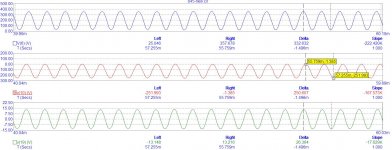
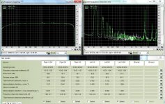
Then I measured main parameters of the amplifier using RMAA software. Results look acceptable if remember that there is NO global negative feedback.
See Pic. 7
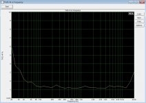
You may notice that there is a lot of hash in the midrange frequencies in spectrum – this is purely because of common mode noise I picked up. Direct measurement of noise level at speaker terminals resulted in only 3.5 mV of hum/noise. I consider it acceptable. And when I was listening this amplifier, I could only hear hum when I put me ear few inches from midrange driver. I also measured THD as function of frequency. Result was mostly a flat graph with distortion rising below 60 Hz and above 15 kHz. This measurement was done at 12.5W of power.
See Pic. 8
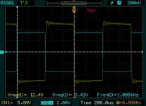
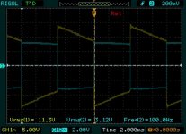
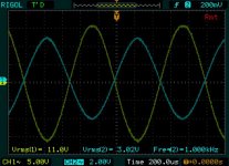
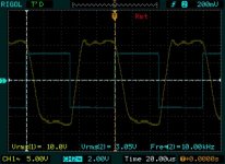
I also looked at how this amplifier reproduces a square wave. As you can expect it demonstrates limits at low and high frequencies. But you cannot expect much more from inexpensive SET amplifier.
See Pic. 9, Pic. 10 and Pic. 11
Some ringing that you can see, is a result of ultrasonic resonance in output transformer. But this is not sign of any instability of the amplifier circuit. I also measured output impedance of that amplifier – it is around 4.7 ohm, that includes about 1 ohm resistance of output transformer winding.
Generally parameters are acceptable for SET type amplifier without negative feedback and considering that circuit is very simple you cannot expect much more.
I also did some additional improvements. This amplifier has analog current meters on the front panel to help set idle current through power tubes. These meters have bright blue lights inside. They are greatly contrasted with the rest of amplifier appearance. I replaced blue LEDs with yellow ones. They almost match light from 845 tube thoriated filaments and now amplifier looks much better in the night. Second is that, as I mentioned above, power transformers in my amplifier were not not potted like they are in the latest version of it. And sitting in quiet listening room I noticed slight mechanical hum from them. Any attempt to tighten bolts that hold transformer core together helped only a little bit. So I decides to convert cage around transformers into full enclosure. I used thin copper sheet with adhesive on one side – got it in local art supply store – and covered all cage from inside with it. This greatly reduced mechanical hum and did not result at excessive temperature of power transformers – it reached only 55C on the cage surface after several hours. I suspect that it is mostly result of heat from power tubes located in just 2” from it.
After using this modified amplifier in my listening room for more than an year, I still keep it. So I consider my effort to make it listenable a success. I do not understand why it couldn't be made that way right from the factory. Thus I wouldn't recommend Chinese SET amplifiers to anyone who is not capable to improve it through DIY. At the same time after improving of original circuit SET amplifier with 845 tube can be used to drive large speakers and reproduce certain type of music in authentic way.
When I wrote about Yaquin, some complained that I didn't provide objective measurement results. Now I decided to add them as proof of my work. So here is an oscilloscope snapshot at onset of clipping.
See Pic. 6
As you can see I was able to get over 11 volts RMS at 8 ohm, which is equivalent to more than 15 Watts, which is close to a theoretical limit of what is possible to get from 845 tube without significant grid current. I actually suspect that there was some grid current, since I noticed that average current through each of power tube was increasing from 95 to 105 mA according to internal meters when I pushed it close to clipping.
Then I measured main parameters of the amplifier using RMAA software. Results look acceptable if remember that there is NO global negative feedback.
See Pic. 7
You may notice that there is a lot of hash in the midrange frequencies in spectrum – this is purely because of common mode noise I picked up. Direct measurement of noise level at speaker terminals resulted in only 3.5 mV of hum/noise. I consider it acceptable. And when I was listening this amplifier, I could only hear hum when I put me ear few inches from midrange driver. I also measured THD as function of frequency. Result was mostly a flat graph with distortion rising below 60 Hz and above 15 kHz. This measurement was done at 12.5W of power.
See Pic. 8
I also looked at how this amplifier reproduces a square wave. As you can expect it demonstrates limits at low and high frequencies. But you cannot expect much more from inexpensive SET amplifier.
See Pic. 9, Pic. 10 and Pic. 11
Some ringing that you can see, is a result of ultrasonic resonance in output transformer. But this is not sign of any instability of the amplifier circuit. I also measured output impedance of that amplifier – it is around 4.7 ohm, that includes about 1 ohm resistance of output transformer winding.
Generally parameters are acceptable for SET type amplifier without negative feedback and considering that circuit is very simple you cannot expect much more.
I also did some additional improvements. This amplifier has analog current meters on the front panel to help set idle current through power tubes. These meters have bright blue lights inside. They are greatly contrasted with the rest of amplifier appearance. I replaced blue LEDs with yellow ones. They almost match light from 845 tube thoriated filaments and now amplifier looks much better in the night. Second is that, as I mentioned above, power transformers in my amplifier were not not potted like they are in the latest version of it. And sitting in quiet listening room I noticed slight mechanical hum from them. Any attempt to tighten bolts that hold transformer core together helped only a little bit. So I decides to convert cage around transformers into full enclosure. I used thin copper sheet with adhesive on one side – got it in local art supply store – and covered all cage from inside with it. This greatly reduced mechanical hum and did not result at excessive temperature of power transformers – it reached only 55C on the cage surface after several hours. I suspect that it is mostly result of heat from power tubes located in just 2” from it.
After using this modified amplifier in my listening room for more than an year, I still keep it. So I consider my effort to make it listenable a success. I do not understand why it couldn't be made that way right from the factory. Thus I wouldn't recommend Chinese SET amplifiers to anyone who is not capable to improve it through DIY. At the same time after improving of original circuit SET amplifier with 845 tube can be used to drive large speakers and reproduce certain type of music in authentic way.
Attachments
Last edited:
Avp1, thanks for the write up. Have you tried operation with the OTs loaded with 8 ohm speakers on the 4 ohm taps?
I too have one of these on a shelf somewhere, purchased non-working for the iron, and my thoughts are similar to yours. Great chassis, very decent iron, ridiculous driver circuit. I don't need to go into the problems with the driver circuit, you have it covered pretty well.
Add to that one additional problem. The OTs measure turns ratios of 26 and 37 for the 8 and 4 ohm windings respectively. These present a 5.4K load to the 845s. I drew that load line and I didn't like what I saw. These transformers are better suited for 300Bs.
If I load it with 8 ohm speakers on the 4 ohm tap, the 845 sees about 11K. That's a much better load line.
So, I know that Mr. Liang sells 300B amps. Did they just mount 300B OTs on this one chassis in error or to get it out the door? Or did they intend to use that load line? If you were to measure your OTs, we would have a second data point.
I have been following TubeLabs PowerDrive circuit closely. The Mr. Liang 845 amp appears to be a very good application for that circuit. And my 5.4K OTs might be better used on a 300B amp.
-Dave
Last edited:
I'd be very concerned that there is insufficient primary inductance for good LF operation with a transformer reflecting 5.4K to the primary.
Might want to consider a GM70 as an alternative output if you can figure out how to get the 20V for filament heating.
(I'm running GM70 into 7K @ 1kV/120mA for ~20W, 5.4K should give you a bit north of 25W)
Might want to consider a GM70 as an alternative output if you can figure out how to get the 20V for filament heating.
(I'm running GM70 into 7K @ 1kV/120mA for ~20W, 5.4K should give you a bit north of 25W)
Avp1, thanks for the write up. Have you tried operation with the OTs loaded with 8 ohm speakers on the 4 ohm taps?
I too have one of these on a shelf somewhere, purchased non-working for the iron, and my thoughts are similar to yours. Great chassis, very decent iron, ridiculous driver circuit. I don't need to go into the problems with the driver circuit, you have it covered pretty well.
Add to that one additional problem. The OTs measure turns ratios of 26 and 37 for the 8 and 4 ohm windings respectively. These present a 5.4K load to the 845s. I drew that load line and I didn't like what I saw. These transformers are better suited for 300Bs.
If I load it with 8 ohm speakers on the 4 ohm tap, the 845 sees about 11K. That's a much better load line.
So, I know that Mr. Liang sells 300B amps. Did they just mount 300B OTs on this one chassis in error or to get it out the door? Or did they intend to use that load line? If you were to measure your OTs, we would have a second data point.
I have been following TubeLabs PowerDrive circuit closely. The Mr. Liang 845 amp appears to be a very good application for that circuit. And my 5.4K OTs might be better used on a 300B amp.
-Dave
I tried 8 ohm load from 4 ohm tap, but it clipped earlier than 8 from 8 for 1 kHz signal. For me bass is OK when running with my speakers (B&W 802D). But I do not try to play bass heavy records with that amp. 1950-60s records with which I mostly use it do not have much down below. 11K will be to much load for only 950-1000 volts at plate. Proper load will be more like 8K. But that for RCA 845. I suspect Chinese version is somewhat different from original. I run tubes at 95-100 mA, which should allow lower load.
The main problem with power drive is where to get negative supply with enough current for driver. I wouldn't use existing bias winding in power transformer - it is nor designed for any significant current. If solve that, it is possible to use 300B as driver directly connected to 845 (capacitor coupled with first tube). I did simulation of that topology and it looks promising with 20-30mA through 300B at idle. Can even use another CCS as load for driver, but it will require significant cooling.
My measurements of transformer gave me 60H/1.6K ohm primary, and 60mH/0.9 ohm secondary (8 ohm tap).
Last edited:
Concerning the midrangey sound and mushy bass, have you considered adding a network across the speakers' terminals to flatten their impedance? I had similar issues when I tried a Chinese EL34 Triode-wired set. A three component network did wonders for making the system listenable with CD music. If you have or can measure the speakers' impedance curves, it isn't too hard to come up with a network design. The entire impedance will be dropped to near the minimum value point in the curve (impedance can only be lowered at places, not raised) but at least in my case the amp played much happier with a more solid sound.
For my purpose - playing vintage records - it actually flattens them and makes more pleasant. I suspect sound engineers of the past mastered for that kind of midrange emphasis in playback system. They rolled off low bass too, to allow decent results on analog tape or vinyl.
Thanks for the suggestions. I am beginning to wonder if the popping sounds had something to do with tube rolling. I replaced all of the stock tubes:
Genelex Gold Lion KT88
EH 6SN7
Genelex Gold Lion 12AX7
As I am burning in the new tubes, the popping is happening less and less.
By the way, this set of tubes sounds significantly better (to my ears) than the stock set.
This amp is a replacement for a $1200 Solid State Amp and there is no comparison. I will be putting the old amp up for sale soon.
The main problem with power drive is where to get negative supply with enough current for driver.
Indeed that is a concern. There is a "low voltage transformer" that supplies the B+ for the 300B and the pentode. IIRC the B+ is about 350+/-. I had considered the use of a couple of silicone diodes to create a negative voltage and a Maida regulator to get the desired negative voltage.
Strike the Madia. With a 900v MOSFET that wouldn't be necessary.
Another approach might be to relocate the coupling cap to the 845 grid and operate the MOSFET gate at Plate voltage and the source at ground. But I'm out of my depth here; comments are appreciated.
Another approach might be to relocate the coupling cap to the 845 grid and operate the MOSFET gate at Plate voltage and the source at ground. But I'm out of my depth here; comments are appreciated.
Last edited:
Mr Liang 845 Output transformer
Hello: I have just inherited a home built copy of the Mr. Liang Audio
Amplifier. The person that built the unit managed to get one channel to
function just fine, the other was blowing speaker coil and it is now suspect
that the output transformer on that channel is breaking down the unit has 845
output tube.
Does anyone on the diyAudio site know of a good source for a replacement pair of output transformer.
I am new to the site so just posting this on a latest Mr Liang link.
Derek Saunders
Unless you find someone in China to send you new transformer, I do not think repair is cost effective option. I suggest to check transformers while disconnected from circuit. Also NEVER test unknown amplifier with real speakers connected to it - always use dummy load. If transformers tested good, it is possible that there is an oscillation. This should be easy to see with oscilloscope.
Mr. Lian 845 - new repair
Quite some time passed since I worked on SET amplifier with 845 tubes (see Mr. Lian 845 SET – more kit rather than commercial product. ). I was happily running it ever since and satisfied with sound quality. But this summer I had to relocate from NJ to TX and amplifier was moved along with my other things. Few days ago I finally completed my music room and install amplifier along with my other audio gear there.
When I turned it on first time I was unpleasantly surprised to hear significant hum in both channels. Originally I thought that it could be cables that pick up noise, but even with cables disconnected hum was still present. The hum was heard in all drivers of my speaker – in bass, mid-range and treble. That pointed to noise being wide range with multiple harmonics of 60Hz power line. None of other devices (including solid state power amplifier) had the issue. Thus it was not a problem with power line either. I had no choice but put tube amplifier back on my work desk. Here I try to share my findings which may help other people dealing with unusually high hum and noise from their tube gear.
I started checking amplifier from output to input. For that I removed main gain stage and driver tubes, leaving only 845 power tubes in place. I also connected 8 ohm dummy load to both channels. In this amplifier output tubes use fixed bias circuit ad there should be no noise/hum at all. But I found unusual hum/noise at the output of both channels. Amplitude was 15 mV in left and 25 mV in right channel. The shape of signal was unstable and not exactly repeatable. It was clear that something is not really right. The source could be either in high voltage supply circuit or bias circuit – nothing else is connected to output tube.
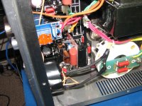
I started testing from high voltage supply. As you can see from a picture below, it consists of rectification bridge and CLC filter with choke and two stacks of capacitors. I used high voltage 100:1 oscilloscope probe to check shape of signal at filter input and output. Though output was sort of good looking, input was significantly asymmetrical. Considering that I already had a bad luck with dead rectifier diodes in it, I decided to replace all diodes in bridge. From the factory it came with 8 (two in each branch) of 2A07. This is a simple rectifier diode, nothing special about them. Considering that it is hard to test diodes in circuit, I decided to get them all replaced. I didn’t find 2A rated diodes in my home stock, so considering that current through bridge never exceed 120 mA, I decided to use 1N4007, which I have plenty available. I cut all 2A07 and soldered 1N4007 instead. When turn on amplifier and checked shape at filer input, it was much more symmetrical and lacked sharp spikes of transients which were present before. I decided to give amplifier a listen and put it back to my system. But I was disappointed again when I tuned it on. Though noise in the left channel was almost gone, right channel was still noisy. On the work bench amplifier went again.
Now I started to check bias circuit. I didn’t find anything unusual in rectifier and filter there all way up to the control grid in right channel power tube. Even with both driver tubes removed there was some strange shaped signal, which was somewhat repeating at power line frequency but included some bursts of high frequency (about 200kHz) on them. Since bias power supply was clean, I started to look for other sources. As you can see from schematic, grid of power tube receives signal from cathode of driver tube via capacitor. I checked, and surely enough, there was that strange signal in the filament (driver is direct heated triode too) circuit in the right channel. Since driver tube was removed, the only source could be a filament supply circuit. As you can see from schematic, it uses rectifier and then a regulator – 7805 with current busting transistor. This power supply is floating against ground and thus hard to analyze with oscilloscope due to lack of reference to ground. When driver tube was not there, I only saw small burst of high frequency noise, but when added 4 ohm resistor simulating load – I saw a huge (2 volts peak to peak) oscillation clearly present. Since there is nothing else other than 7805 and transistor that could cause this, I decided to replace both with new ones. I did that and also added 0.1uF capacitors between both input and output terminals 7805 and ground. After that change there was no more bursts of oscillation visible. When I put amplifier back together and put back in my system – it was almost silent – no noise, hum or anything else.
Knowing that case can help someone who deals with unusual noise or hum in tube or other gear with busted 7805 regulator. In this case oscillation developed over time, so it was not that existed originally. Usually 78xx regulators are very stable, but when used along with current buster seems to be more prone to oscillation. This is often hard to catch if you do not use digital oscilloscope with long enough memory to cover few periods of power line frequency and have enough sampling points to resolve 200kHz bursts superimposed on it.
Generally I am not really satisfied with quality of components in this Chinese amplifier – input tube died while I was experimenting with circuit change, I already replaced rectifier diodes in power tube filament supply now rectifiers in high voltage supply and filament regulator also failed (or should I say degraded). Better quality components are needed to work in harsh environment close to heated tubes and operating at high voltage and current
Quite some time passed since I worked on SET amplifier with 845 tubes (see Mr. Lian 845 SET – more kit rather than commercial product. ). I was happily running it ever since and satisfied with sound quality. But this summer I had to relocate from NJ to TX and amplifier was moved along with my other things. Few days ago I finally completed my music room and install amplifier along with my other audio gear there.
When I turned it on first time I was unpleasantly surprised to hear significant hum in both channels. Originally I thought that it could be cables that pick up noise, but even with cables disconnected hum was still present. The hum was heard in all drivers of my speaker – in bass, mid-range and treble. That pointed to noise being wide range with multiple harmonics of 60Hz power line. None of other devices (including solid state power amplifier) had the issue. Thus it was not a problem with power line either. I had no choice but put tube amplifier back on my work desk. Here I try to share my findings which may help other people dealing with unusually high hum and noise from their tube gear.
I started checking amplifier from output to input. For that I removed main gain stage and driver tubes, leaving only 845 power tubes in place. I also connected 8 ohm dummy load to both channels. In this amplifier output tubes use fixed bias circuit ad there should be no noise/hum at all. But I found unusual hum/noise at the output of both channels. Amplitude was 15 mV in left and 25 mV in right channel. The shape of signal was unstable and not exactly repeatable. It was clear that something is not really right. The source could be either in high voltage supply circuit or bias circuit – nothing else is connected to output tube.
I started testing from high voltage supply. As you can see from a picture below, it consists of rectification bridge and CLC filter with choke and two stacks of capacitors. I used high voltage 100:1 oscilloscope probe to check shape of signal at filter input and output. Though output was sort of good looking, input was significantly asymmetrical. Considering that I already had a bad luck with dead rectifier diodes in it, I decided to replace all diodes in bridge. From the factory it came with 8 (two in each branch) of 2A07. This is a simple rectifier diode, nothing special about them. Considering that it is hard to test diodes in circuit, I decided to get them all replaced. I didn’t find 2A rated diodes in my home stock, so considering that current through bridge never exceed 120 mA, I decided to use 1N4007, which I have plenty available. I cut all 2A07 and soldered 1N4007 instead. When turn on amplifier and checked shape at filer input, it was much more symmetrical and lacked sharp spikes of transients which were present before. I decided to give amplifier a listen and put it back to my system. But I was disappointed again when I tuned it on. Though noise in the left channel was almost gone, right channel was still noisy. On the work bench amplifier went again.
Now I started to check bias circuit. I didn’t find anything unusual in rectifier and filter there all way up to the control grid in right channel power tube. Even with both driver tubes removed there was some strange shaped signal, which was somewhat repeating at power line frequency but included some bursts of high frequency (about 200kHz) on them. Since bias power supply was clean, I started to look for other sources. As you can see from schematic, grid of power tube receives signal from cathode of driver tube via capacitor. I checked, and surely enough, there was that strange signal in the filament (driver is direct heated triode too) circuit in the right channel. Since driver tube was removed, the only source could be a filament supply circuit. As you can see from schematic, it uses rectifier and then a regulator – 7805 with current busting transistor. This power supply is floating against ground and thus hard to analyze with oscilloscope due to lack of reference to ground. When driver tube was not there, I only saw small burst of high frequency noise, but when added 4 ohm resistor simulating load – I saw a huge (2 volts peak to peak) oscillation clearly present. Since there is nothing else other than 7805 and transistor that could cause this, I decided to replace both with new ones. I did that and also added 0.1uF capacitors between both input and output terminals 7805 and ground. After that change there was no more bursts of oscillation visible. When I put amplifier back together and put back in my system – it was almost silent – no noise, hum or anything else.
Knowing that case can help someone who deals with unusual noise or hum in tube or other gear with busted 7805 regulator. In this case oscillation developed over time, so it was not that existed originally. Usually 78xx regulators are very stable, but when used along with current buster seems to be more prone to oscillation. This is often hard to catch if you do not use digital oscilloscope with long enough memory to cover few periods of power line frequency and have enough sampling points to resolve 200kHz bursts superimposed on it.
Generally I am not really satisfied with quality of components in this Chinese amplifier – input tube died while I was experimenting with circuit change, I already replaced rectifier diodes in power tube filament supply now rectifiers in high voltage supply and filament regulator also failed (or should I say degraded). Better quality components are needed to work in harsh environment close to heated tubes and operating at high voltage and current
Attachments
 Multiple threads on the same topic have been merged.
Do you work on tube amps for side jobs?
This is a hobby for me. I usually do not do commercial work unless I am interested in some new circuit.
AVP1 you said you covered the cage inside with copper tape to reduce hum.
Do you have a picture? Could you describe more in detail how you did it?
I use to wind copper tapeon the transformer to make a short turn, and it should go in the same plane as the winding but outside the the transformer core. I´ll guess you also place the copper winding inside the cage in that same plane?
In my case the goal was to reduce MECHANICAL hum from transformers. Cover that came with amplifier has cut slots, likely for better cooling. Noise from both power transformers was escaping freely through them. I bought copper foil with adhesive on one side from craft store (can't recall which one - likely Hobby Lobby). I attached that foil from inside to the cage, blocking slots and thus noise. Cover gets hot after hours of work, but not too hot to worry about. I think it is mostly heated by IR radiation from power tubes in two inches from it.
Later editions of this amplifier use covers for power transformers that look exactly like ones for output transformers. In that case this mod is not necessary.
Later editions of this amplifier use covers for power transformers that look exactly like ones for output transformers. In that case this mod is not necessary.
- Status
- This old topic is closed. If you want to reopen this topic, contact a moderator using the "Report Post" button.
- Home
- Amplifiers
- Tubes / Valves
- Mr. Lian 845 SET – more kit rather than commercial product.