Pretty straight forward… nothing really wrong with it.
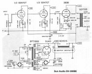
The use of a 62 kΩ load resistor for 6SN7 stage 1 is (280 - 70 = 210 V); P = E²/R = 210² ÷ 62,000 = ¾ watt. 1 watt design is OK. E = IR … I = E/R is 210 ÷ 62,000 = 3.4 ma. This goes thru stage 1's 470 Ω, P = I²R = 0.005 W. Quite low. nothing wrong there. There's only a 1.5 volt drop across the cathode resistor.
The next stage is more or less OK. Appropriate values. For the anode load, 280 - 210 = 70 volts. 70² ÷ 27000 = 0.18 W, so it is unclear why a 2 watt resistor is specified. For that matter, the same goes for stage 2's cathode resistor. Over-specified. (Seems like the persons doing the calculations might have missed a decimal point. 0.18 × 10 → about 2 watts).
The 0.22 µF coupling capacitor is OK. It should be rated at 350+ volts tho', and is not specified. Quite a bit of DC blocking to perform. There's no listing for how much the 300 B filament/cathode is going to e raised by the 1 kΩ resistor, largely 'cuz one can't deduce how much DC resistance the output transformer has on its primary. Impedance is not resistance. But let's say "its about right". Could be.
Then that wraps up the amplification section.
Power supply… looks pretty nominal although it isn't clear why it has two 300 B filament DC supplies. For left-and-right channels, as this mightn't be a monoblock? I'd go with that.
The twin-cap-in-a-can has 47 µF on the 5U4G side, which to me seems like a pretty high capacitance for the vacuum rectifier. But who knows. Might not be wrong. I personally would be down toward 22 µF on the direct-rectification side, and 100 µF on the post-choke side. But that's just me. Others will disagree, I am certain.
So, I see little-to-no basic problem with this diagram.
You don't even need a spreadsheet, let alone SPICE to get "the numbers".
Just saying,
GoatGuy
The 6,3V winding for the 6SN7 needs a DC reference and not be left floating.
The 300B sound better with AC heating instead of this roughly filtered DC. Even better is regulated DC (I'm not getting in the current Vs voltage regulation discussion here). You need a higher AC voltage to start with to feed the regulator.
The 300B sound better with AC heating instead of this roughly filtered DC. Even better is regulated DC (I'm not getting in the current Vs voltage regulation discussion here). You need a higher AC voltage to start with to feed the regulator.
This schematic is old as the hills - well old enough that I remember it from the Sound Practices day.
These days I prefer a good solid pentode driver, like Thorsten Loesch's Legacy 300B using an EL84/SV83, or a C3m.
http://community.fortunecity.ws/rivendell/xentar/1179/projects/legacy/Legacy.html
These days I prefer a good solid pentode driver, like Thorsten Loesch's Legacy 300B using an EL84/SV83, or a C3m.
http://community.fortunecity.ws/rivendell/xentar/1179/projects/legacy/Legacy.html
Im planning to build it with CV181Z at input and 300B shuguang or sophia royal princess. Can anyone tell me as I read somewhere that something is wrong with this circuit.
Yes there is. If the plate of the first triode is at 70V then so will be the grid on the second. That means the cathode of the second triode will at 70+bias. Because the plate and cathode resistors for the second triode are identical the voltage drop on the plate resistor cannot be 70V but has to be 70+bias. So don't take those values for precise values but only as very approximate ones....
There might tolerances on the resistors but they have to be really badly selected 10% tolerance resistors to get 70+bias at the cathode and only 70V at the plate.
In general that circuit is more suitable for a 2A3. The second triode works at less than 3 mA current which means that for about 55V peak needed drive the 300B it will distort a lot almost running out of current. This circuit would work infinitely better with a good interstage transformer for the second triode so that it could be run at something like 200V/7-8mA. That would be possible because the transformer will not cause any huge supply voltage drop for 7-8 mA current and sensible primary load impedance can be achieved anyway.
Last edited:
Well yes … yet it is symmetric (70 V + bias on either side)
The margin (0 + 70 + bias … 280 - 70 - bias … is about (280 - 0) - 2 × (70 + bias). At 27 kΩ cathode and anode loads, and a 'spec' of basically about –70 volts drop on section 2's anode from 280 to 210, I = E/R = 70 ÷ 27000 = 2.6 ma. The VGK will be about 6 V for a 6SN7G at 2.6 ma and 140 volts VAK. So … the actual VK relative to ground quiescent is 70 ⊕ 6 = 76 volts. Likewise the VA is 280 - 70 - 6 = 204 V. Within 10% of the predicted "dumb calc" numbers.
Good enough.
I remain convinced there's nothing fundamentally wrong.
Oh, precision is off! for sure. But well within design spec.
GoatGuy
For a reliable operation the second triode of the 6SN7GT should be AC coupled. This involves the addition of a capacitor in series from pin 1 ( grid) to pin5 (plate) of the first triode section and a grid resistor from pin 1 to ground. The cathode resistor will also need to be lowered in value.
sorry folks......two stages of voltage gain is one stage too many, imho.....
if you can do it in one, why not? D3a wired in triode is a good tube to use...
i have also used the 12hl7 also triode wired, with good results...
simplicity is best, just one coupling cap in the signal path is best for me...
if you can do it in one, why not? D3a wired in triode is a good tube to use...
i have also used the 12hl7 also triode wired, with good results...
simplicity is best, just one coupling cap in the signal path is best for me...
The two cascaded DC coupled 6SN7's can work well with low distortion however the power supply should be adequate. That would also imply that the 300B is used more efficiently. For example one could have about 440V, where some volts are lost in heat, 350V are for anode voltage and about 75V cathode bias for 60 mA current. A proper 300B amp without stressing the tube. It can be Any 300B running like this.
This way the first triode can have higher plate voltage, say 125V, and the second as well and more importantly with more current. It could be about 160V plate voltage at 6 mA with 22K for both plate and cathode, for example, running quite more linearly despite the large swing needed. The input voltage for full drive will be around 0.3 Vrms. That's a true integrated amp the would work fine Wanting less gain one could also have the possibility to add some feedback.
This way the first triode can have higher plate voltage, say 125V, and the second as well and more importantly with more current. It could be about 160V plate voltage at 6 mA with 22K for both plate and cathode, for example, running quite more linearly despite the large swing needed. The input voltage for full drive will be around 0.3 Vrms. That's a true integrated amp the would work fine Wanting less gain one could also have the possibility to add some feedback.
sorry folks......two stages of voltage gain is one stage too many, imho… if you can do it in one, why not? D3a wired in triode is a good tube to use… I have also used the 12HL7 also triode wired, with good results… simplicity is best, just one coupling cap in the signal path is best for me…
There is something to be said for that, I'll grant.
Yet, taking a really expensive lesson from my short days as a semiconductor lithography optical-path specialist, it was fairly quickly learned that the way to build a near-perfect chip optic was to not ask any particular element inside “a stack” to do much light-bending. The more bending per element, the more intrinsic non-linearities of the glass would compound into an ever-so-unhelpfully-out-of-focus(able) lens. More elements, less bending per element.
This is why modern day low-nanometer litho equipment has lenses that cost in excess of $3,000,000 each! Because they're made from 20 or more HUGE pieces of high-precision composition rare-earth glasses, milled to curvatures of a fraction of an arcsecond in sphericity (or non-sphericity).
ANYWAY,
About 10 years back, I breadboarded a number of experiments having variously more stages of less-significant amplification per stage, compared to fewer stages having more amplification per. Some of the experimentation was done with sand-based devices (mostly BJTs and JFETs.) Some was done with the cosmic comedy of vacuum tubes I have accumulated over the decades. ALL was done with quite a bit of care in selecting non-active components — excellent capacitors, excellent resistors, fine-trimming of resistor values (with small series resistors, fixed) and so forth.
Both the spectrum analyzer and the Good Old Ear confirmed my conjecture: more stages, with substantially lower gain per stage, resulted in substantially more well controlled distortion (and lowered in general). One could clearly overdo the idea (at 5 stages distortions began to increase), but one could easily also "under-do" them too.
So, that's my hard-won takeaway.
Maybe The Constabulatory here has a different opinion.
I'd expect so!
But that's mine.
Just saying,
GoatGuy

Have you ever wondered why you got a little less output power than you expected? Or that there was a little more distortion at the power you were shooting for? Sometimes we forget that the output transformer has an insertion loss.
If the transformer has a loss of 1 dB, then 6 Watts from the tube becomes 4.77 Watts out of the transformer.
A transformer with only 0.5 dB loss is very good. For 0.5 dB loss, 6 Watts from the tube becomes 5.35 Watts out of the transformer.
If the transformer has a loss of 1 dB, then 6 Watts from the tube becomes 4.77 Watts out of the transformer.
A transformer with only 0.5 dB loss is very good. For 0.5 dB loss, 6 Watts from the tube becomes 5.35 Watts out of the transformer.
i just shared my opinion, take or leave it...
i am not saying mine is superior, just simple...
and that it works...
the 6sn7 thing is old school as the williamson amps.
the antique sounds lab of hong kong makes amps using the 6sn7's....
Sorry Tecson but I strongly disagree. I don't think the Sun Audio is complicated at all. It's actually quite simple as are most kits. And the 2-stage amp is even older school except that when it was invented high gm pentodes didn't exist. So they used signal pentodes as pentodes. Triode-strapping sometimes is good or convenient sometimes isn't....it's not a school......
^of course, be my guest and disagree....that is fine....
if you read and understood what i said, i said that two stages of voltage gain is one too many, that is what i said, if you find more in what i said, that is not me...... but that is just me....
a pentode run in pentode mode is a pentode, connected as a triode is a triode, again this is me...
if you read and understood what i said, i said that two stages of voltage gain is one too many, that is what i said, if you find more in what i said, that is not me...... but that is just me....
a pentode run in pentode mode is a pentode, connected as a triode is a triode, again this is me...
- Status
- This old topic is closed. If you want to reopen this topic, contact a moderator using the "Report Post" button.
- Home
- Amplifiers
- Tubes / Valves
- whats wrong with this 300b SE schematic?