Tony Tecson,
That I why I stated that about all anybody would get might be 9.85 Watts (and less than that because of the output transformer loss).
And that would be with 3.5k primary, not the 2.5k in the schematic.
Posts # 36 and # 37.
oh, but you need not really had to explain to me, i got you the first time...
i thought class A tube output is based on 25 to 30% of plate dissipation, that's all...
but then in class A2 who knows?, i have not tried it, maybe those who have tried can chime in and enlighten us....
")
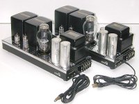
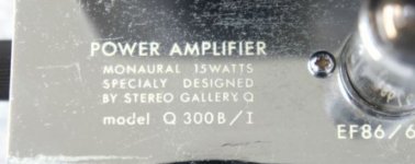
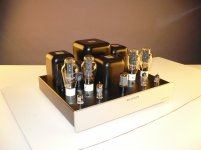
stereo gallery Q 300B
6A3sUMMER ,you are right . 54ma/170v-p/4w are values issued from simulation of 300B version of this 2A3 conceived amplifier. The kit quality OPT must retain 10% to deliver 3.6w , as PRR predicted.
If you have a second look at -100v curve , you will see at 450v plate the 300B swallows 100ma blushing 45watts , -98/440v should heat 44watts . Yes this is 10% "overlocked" . To remind that this is a professional use amp intended for Japanese tea houses where the appreciated item was not the tea but the HIFI sound . If the life cycle of WE300B 10000hrs is reduced to 5000hrs ,150USD costing by then in 80's was still a bargain if it attracted more customers.
Nowadays Shuguang produces 60watt version of this tube as 300B-C and the prestigious 300B-Z costing 110USD + shipment from Leisure_audio .
The stereo gallery Q 300b amp is presented in Jean Hiraga's book as 20watt with 1% distortion and 6db NFR if I do remember well , but in his book most circuit diagrams are purposely modified to bypass copyright problems . As this amp is contemporary to book's publication, look at it with doubt. In most cases the introduced error is so rough, as shorted cap or wrong wired bias ,that anyone with some knowledge can sort it out.
Attachments
stereo gallery
The power as the picture shows is 15w but by using Shuguang 300B-C or 300B-Z it is possible to obtain 20W .
300B-C long-life design, use pure graphite anode and plate power dissipation can reach up to 60W. If you adjust the design parameters properly, single tube can be used as class A amplifier, and can delivery output power higher than 20W.
Extract from general catalog.
Attachments
Class A SE output stage is typically biased at 100% Pdiss-max to get the most output power possible.i thought class A tube output is based on 25 to 30% of plate dissipation, that's all...
The power as the picture shows is 15w but by using Shuguang 300B-C or 300B-Z it is possible to obtain 20W .
300B-C long-life design, use pure graphite anode and plate power dissipation can reach up to 60W. If you adjust the design parameters properly, single tube can be used as class A amplifier, and can delivery output power higher than 20W.
Extract from general catalog.
To make it work fine at more than 40W plate dissipation you need more filament power and better cooling otherwise tube life will be very short.
In 60-65W 300B's like the EML 300B-XLS or 320B-XLS the filament specs are 5V 1.5A and 1.7A, respectively. Standard 300B needs 5V 1.2A.
The 300B-z is a very good 300B but it is has the saae specs as the original except the max plate voltage is 480V instead of 450V.
Working at 35-40W with the original 300B or other similar tubes useful life might be well under 5000h.
Max 100mA quiescent plate current is possible with self-bias or adjustable fixed bias. 70 mA is max current with non-adjustable fixed bias.
Other tubes derived from 300B like the JJ 2A3-40 have identical specs, those with mesh plates have max plate dissipation of 26-28W depending on the brand.
No idea about the 300B-C but if this has filament working at 5V 1.2A like the standard 300B I doubt it can be considered a 60W tube.
The JJ 2A3-40 is a perfect JJ 300B with filaments at 2,5 volt and it is a good tube.
The 300B-C is a "sport" version of 300B, it has a bold grafite anode, I used it seems to be strong but maybe we can't consider it as a 300B same of the other variants listed on this thread
In addition there is the mesh anode type that can dissipate 28 watt
On the W.E. book there are a long list of working point about 300B.
With fixed bias the max current is 70 mA, the max power is 40 watt, these are the official data.
Walter
Regarding the schema at post 1, if you have a 6SN7 I can suggest the solution of AudioNote kit 1 with 300B, 5687 in srpp as drive and one half of 6SN7 as gain. It is a good solution with a strong capability to drive at the best the grid of 300B . The bias is a cathode bias.
Walter
Walter
One user made the same circuit and says it sounds very good over this forum:
DIY Audio Projects Forum • First DIY amp FINISHED - 300B SET - works!
DIY Audio Projects Forum • First DIY amp FINISHED - 300B SET - works!
Gentlebeings- the WE 300A datasheet shows about all legal and sensible operating conditions. (The difference A/B is the base, not the insides.)
http://www.mif.pg.gda.pl/homepages/frank/sheets/136/3/300A.pdf
I have extracted the "Maximum Operating Conditions". You can get 17.8 Watts (with somewhat high THD).
Relative to the 300A's max ratings, we are AT max V and max I but 10% shy of plate dissipation. (The later 300B sheet shows slightly different max.)
If I had a money-making Hi-Fi "tea" shop, and the other shop in town was louder, I would have little fear in shoving these conditions up 6% (477V 85mA 40.5W Pdiss) to get another half-dB and a "20 Watts!!" boast-point. If it brings in another 26 Yen per hour it will pay-off the possibly reduced tube-life.
Attachments
PRR if the target is 20W and taking into account tube life there is a better option: 300B PSE. Among the several 300B amps I have had in my hands (4 built from scratch and others just modified, all of them for other people) this is surely my favourite.
The output stage works as follows:
1) 420V/75mA for each 300B.
2) 2.5K/8R transformer with just 0.2 dB power loss.
3) Class A1 full drive about 87V peak, relatively easy Class A2 drive up to 95V peak (a proper cathode follower works really well).
OK, two tubes consume 75VA vs 46.5VA in your example but tube life is more than twice. Easily. So cost difference is small. The original Western Electric tubes are quite expensive but they really deliver what it says on the box and if WE never suggested more 36W plate dissipation there is good a reason. Less expensive 300Bs might perform at the very same level but last less! In my experience good tube life for most brands is achieved with max 32W plate dissipation. Below 30W can be surprisingly long for some of them....
The performance of the power stage above into 8 ohm is: 16W Class A1 at max 3% THD, 20W Class A2 at 5% THD. This is not the max power. Max power is achieved into 6 ohm which is a typical minimum impedance for well behaved loudspeakers. The output power into 6R is 20W Class A1 at 5% THD and 25W in Class A2 at 7% THD. THD was measured at 100Hz and 1000Hz. Negligible difference.... Didn't measure at higher frequency because of the 25KHz limit of HP analyser.
The amplifier has really low distortion at low and medium levels and doesn't need any feedback. If one works with primary loads of 2.5K or less per tube very likely will need some feedback.
Another option, as already I said, are 50-60W 300B's on steroids....
454,
Now you are talking good tested ideas! PSE 300B.
Versus a SE 300B: All you need are more a capable power supply, a more capable output transformer, a driver that can drive 2X the miller capacitance, and one extra 300B per channel.
By the way, the driver only needs to swing the same peak to peak voltage as the driver for the SE 300B amp. And (horrors), you can parallel the driver tube and get that extra current to drive the 2X miller capacitance. Just follow the rules given in the article mentioned below, for both paralleling the driver tube, and the output tube. Pick your favorite driver tube, and your favorite output tube, build it, and enjoy.
The [definitive] article for parallel tubes was "Paralleling Tubes Effects", Glass Audio Volume 12, Number 5, 2000. It had 600 measurements and analyzed and collated data; 3 listening venues; Taylor Series Math; and a discussion on vacuum tube element spacing (relative dimensions).
Last edited:
In every case is much better to use two 300B in push pull instead PSE. First the efficency is quite the double, the OT is less expensive and the power output is around 22 watt/8 ohm in a well done diagram. Without the A1 or A2 driving. The driving stage is not so complicate respect the PSE. But must be quite perfect. With fixed bias at 420 Vdc and 50 mA of bias we can reach around 5-6 watt in full class A with a low THD. The OT can with a ratio of 20:1 a-a In attach the first version on pp Then the curve of 300B JJ traced with my Sofia
Walter
Walter
Attachments
waltube,
Of course push pull can have more power, and can have less a expensive output transformer.
Depending on the exact topology of driver that you pick, Either the push pull driver, Or the single ended driver, will be more complicated than the driver for the other type of output stage (SE / PP).
I have used single triode drivers, and properly implemented parallel triode drivers, to drive SE output stages. Each has its tradeoffs, but these do not have to be complex.
Some people want to build SE instead of Push Pull (for many different reasons). I have built many SE and many PP.
But this thread was about Single Ended, not Push Pull.
For Push Pull drivers: I have used triode voltage gain plus triode concertina; 'serial' triode phase splitters; and true constant current long tail for triode cathode-coupled phase splitters. Each of these topologies has its tradeoffs and advantages, but I find these to be a little more complex (than SE drivers), because of the requirements to properly drive push pull output tubes.
'Serial' phase splitters tend to have the most gain, but with other tradeoffs, including the fact that one phase is driving one output tube with more 2nd harmonic distortion than the outer phase's second harmonic distortion.
I prefer the cathode coupled phase splitters with true constant current in the cathode circuit; the balance of gain and phase is very good, the distortion is very good, but with half the gain and dynamic range of a 'serial' phase splitter.
I do not like the typical concertina phase splitter. One reason is the large cathode voltage elevation for DC coupled gain to concertina (and otherwise with AC coupling with an added RC network).
But that is push pull, not SE.
Walter, the class A2 operation is just a consequence of the driver choice (i.e. DC coupled cathode follower). This way blocking distortion is completely removed too. Overall a better choice respect to fixed bias with RC coupling, IMHO.
If I want to use RC coupling then I prefer cathode bias. I have done this too. It was a 3-stage amp with 2 tubes: PCL82 + 300B. Not bad at all but the PSE is at least one step above and not just for the higher power.
If I want to use RC coupling then I prefer cathode bias. I have done this too. It was a 3-stage amp with 2 tubes: PCL82 + 300B. Not bad at all but the PSE is at least one step above and not just for the higher power.
The 300 PSE above has about 150 pF Miller capacitance (which also takes into account some parasitics) and does not require more than 0.3-0.4W peak power drive. I did it with half 6BX7 per channel (the 6BL7 would be good too) running at 330V plate voltage and 15 mA from +/-240V supply. Could drive at full power up to 25 KHz without problems. Around 35 KHz still going ok but distortion starts to go up quicker looking at the sinusoids. It could be even better with active loads and/or non-symmetric supply but it worked well and was simpler (basically like the SE but different tube and supply).By the way, the driver only needs to swing the same peak to peak voltage as the driver for the SE 300B amp. And (horrors), you can parallel the driver tube and get that extra current to drive the 2X miller capacitance. Just follow the rules given in the article mentioned below, for both paralleling the driver tube, and the output tube. Pick your favorite driver tube, and your favorite output tube, build it, and enjoy.
The [definitive] article for parallel tubes was "Paralleling Tubes Effects", Glass Audio Volume 12, Number 5, 2000. It had 600 measurements and analyzed and collated data; 3 listening venues; Taylor Series Math; and a discussion on vacuum tube element spacing (relative dimensions).
I have also used paralleled tubes (6SN7) to drive a 2A3 PSE output stage. If the tubes are well selected is really hard to spot the difference respect to individual cathode followers each driving one power tube. Where can I find that article? I am curious.
Last edited:
- Status
- This old topic is closed. If you want to reopen this topic, contact a moderator using the "Report Post" button.
- Home
- Amplifiers
- Tubes / Valves
- whats wrong with this 300b SE schematic?