You wrote that one gain stage is best because simplicity is best. The second part is where I disagree because it is not general. I call that an opinion based on arbitrary statement. It's different. If you can't figure it out I can't help....that's all.aren't we all? and why do i need to kowtow to you?
did i just told you that you can disagree?
why do you have to rebut opinions that run contrary to yours? and who needs your help? there are a lot of gurus here to learn from, just read and read and read, and then build and build and build and then have a listen....if success good...if not do it again....this is diy where folks have fun doing things instead of arguing and arguing...
i am not one to tell people how they should think....
i am not one to tell people how they should think....
Using no bypass capacitors, cathode 'bias', I arrange my gain stages either as
That multiple lower-gain stages, especially if run at 70% or so of valve PK (plate dissipation) is a pretty sweet chain. 60× or so gain covers "the usual input signals" fairly handily. ±1 VRMS becomes 1.414 × 60 → 85 VPP or thereabouts. Plenty to drive the finals like 300*B
But again, that's me.
I also like “mixed mode”: using either a solid BJT or MOSFET as the phase splitter if going into a push-pull output topology. They're remarkably linear. Pentodes turn out to do well when called into service in the phase splitter.
Anyway, just more thoughts to add to the discussion.
GoatGuy
10 × 4 × 1.5 = 60× → +35 dB … or …
7 × 3 × 2 × 1.4 = 59× → +35 dB with the idea (as before)
7 × 3 × 2 × 1.4 = 59× → +35 dB with the idea (as before)
That multiple lower-gain stages, especially if run at 70% or so of valve PK (plate dissipation) is a pretty sweet chain. 60× or so gain covers "the usual input signals" fairly handily. ±1 VRMS becomes 1.414 × 60 → 85 VPP or thereabouts. Plenty to drive the finals like 300*B
But again, that's me.
I also like “mixed mode”: using either a solid BJT or MOSFET as the phase splitter if going into a push-pull output topology. They're remarkably linear. Pentodes turn out to do well when called into service in the phase splitter.
Anyway, just more thoughts to add to the discussion.
GoatGuy
I only said that I disagree and gave a CLEAR explanation. This is just a pointless rant of yours without any logic.why do you have to rebut opinions that run contrary to yours?
and who needs your help? there are a lot of gurus here to learn from, just read and read and read, and then build and build and build and then have a listen....if success good...if not do it again....this is diy where folks have fun doing things instead of arguing and arguing...
For the rest, that's YOUR diy.
i am not one to tell people how they should think....
I never wrote that. That's actually what YOU are doing!!! Simply disgraceful and disgusting.
I only said that I disagree and gave a CLEAR explanation. This is just a pointless rant of yours without any logic. For the rest, that's YOUR diy. I never wrote that. That's actually what YOU are doing!!! Simply disgraceful and disgusting.
So…boys'n'girls … could the both of you stop? Thank you in advance.
GoatGuy
...320V minus near 60V wasted....!
You are correct; I missed that.
So 3.6 Watts.
As a 150Watt guy myself, I'm not impressed by the difference 5.5W or 3.6W. Both are fine for soft listening (medium levels on very efficient speakers).
You are correct; I missed that.
So 3.6 Watts.
As a 150Watt guy myself, I'm not impressed by the difference 5.5W or 3.6W. Both are fine for soft listening (medium levels on very efficient speakers).
can you tell us what 150 watt amp is that?
i am making a 4D32 pp amp for 120 watts....
 45, take it down a notch. Please remain respectful to your fellow forum members.
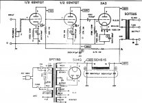
With reference to Post # 35, versus the 300B family of curves on the Western Electric 300B data sheet:
300B SE, 440Vplate to filament, Bias -96V, 75mA, 33W plate dissipation, 3.5k primary.
Watts peak = I(squared) * R
Watts rms = (I(squared) * R)/2
That calculates to 19.69 Watts peak, 9.85 Watts rms.
20 Watts, in A2? That would require + 107mA more than 75mA; and -107mA less than 75mA into 3,500 Ohms. The quiescent current is only 75mA. 75 - 107 = -32mA that the circuit does not have. Won't the tube be cut off during part of the cycle at the 20 Watt rms level? i.e. from 75mA to 0 ma and then 32mA less than that.
Last edited:
kokoriantz,
I am always interested in how to get more power out of single ended amplifiers.
For your post #30, how did you get the numbers you listed, versus 300B and 2.5k primary in the schematic? Were they measured, or calculated? At what distortion level?
Was the 300B connected to the 3.5k primary, instead of the 2.5k primary? 4 Watts seems more possible that way.
I often get disappointed at the output watts in my SE amps, until I remind myself of the 0.5 or 1 dB loss of the output transformer. I expected 2.5 Watts from an output tube of a small power SE amp, but only got 2 Watts. But that was explained by the 1 dB loss of the output transformer. A 3500 Ohm primary with 175 Ohm DCR, and a 4 Ohm tap with 0.2 Ohm DCR has 1 dB of power loss. And the 0.2 Ohm DCR is hard to measure properly unless you have a 4 wire Ohmmeter.
Thanks!
Last edited:
- Status
- This old topic is closed. If you want to reopen this topic, contact a moderator using the "Report Post" button.
- Home
- Amplifiers
- Tubes / Valves
- whats wrong with this 300b SE schematic?