I'm going to do that!
I have a couple of projects that must be done and a riaa to a friend then I can start with Big blue as I named the project to. I have already put down EL86 and other components that I had at home in a project box otherwise it is easy that some component ends up somewhere else. The next step is to make a description of which components are needed and above all where to sit in the amplifier it is so much easier to build then.
Anders
I've got a stash of perforated aluminum for a top plate, a pair of 3k:4ohm output transformers, and some purpleheart wood as well as wenge wood set aside for another build using these at some point ")
Just need to build a router table and table for my saw, then have the time to actually build
Just need to build a router table and table for my saw, then have the time to actually build
Just need to build a router table and table for my saw, then have the time to actually build
Harbor Freight in Concord?
Harbor Freight in Concord?
Going to build them myself, and bolt the router or saw directly to them
Lots of good youtube videos to follow for them.
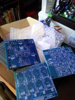
Ordered a set of ten boards, I'll build up a pair and see how they do
If there are no major issues I'll post up files and maybe sell a pair or so of boards from what I wont use.
Ordered a set of ten boards, I'll build up a pair and see how they do
Congratulations with the progress
Hope your build performs well and sounds great.If there are no issues I’m in line for a pair of PCBs.
Francois
Last edited:
Thinking I'll go triode connected on this first one, since I have so many 6p43p-e on hand. I have the parts to do a set of monoblocks just need to build some enclosures
Time permitting, of course
Man, I really like the blue PCBs, definitely going with blue from now on.
I'll start up on digging out parts to populate these, going with monoblocks since I have some cheap transformers on hand that will work well.
Time permitting, of course
Man, I really like the blue PCBs, definitely going with blue from now on.
I'll start up on digging out parts to populate these, going with monoblocks since I have some cheap transformers on hand that will work well.
Attachments
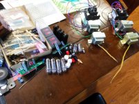
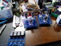
Started populating a pair, just need to dig out my larger power resistors to finish up, and I'm out of screw terminals so need to grab some. Some minor mistakes but nothing too bad (silly stuff really)
Found six Russian caps that were a perfect fit for this build
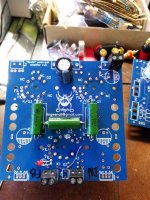
Short list of errors (which have so far been corrected on the design file just now)
Somehow the GND end of the input resistor (R3) wasn't connected to anything. Easy fix, run a trimmed-off resistor lead to a nearby ground pad. Fixed.
Cathode pin of the input tube socket (K2) was somehow grounded. Simply cut the traces on the bottom of the board to isolate it from ground, as the signal wiring is topside for this section of the circuit otherwise. Easy fix.
Feedback capacitor (Cfb) has no traces joining it across the feedback resistor. Will need to run leads from the feedback resistor to attach. Easy fix.
Silkscreen for power input terminal disappeared.
Small R10 should read R14 (grid resistors for output tubes)
Since I'm using EasyEDA I think I've found a bug- on occasion GND nets will merge by accident, and some traces will simply disappear entirely- I've noticed this on several occasions, with different computers and PCB files. I had a run of LED driver (aquarium/horticultural lighting) PCBs done not too long ago that had a similar issue with GND pins simply being tied to nothing. Easy fix, but a little frustrating.
This is why I like to test things before sending things out- and don't promise boards or take any sort of prepay until things are verified. On the bright side I'll have a couple pairs of bards to sell off dirt cheap soon as soon as I finish these up to document any additional errors.
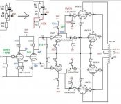
Apparently I had attached a schematic earlier with the basic loadout of the board, but I'll share it here again for posterity-
Found six Russian caps that were a perfect fit for this build
Short list of errors (which have so far been corrected on the design file just now)
Somehow the GND end of the input resistor (R3) wasn't connected to anything. Easy fix, run a trimmed-off resistor lead to a nearby ground pad. Fixed.
Cathode pin of the input tube socket (K2) was somehow grounded. Simply cut the traces on the bottom of the board to isolate it from ground, as the signal wiring is topside for this section of the circuit otherwise. Easy fix.
Feedback capacitor (Cfb) has no traces joining it across the feedback resistor. Will need to run leads from the feedback resistor to attach. Easy fix.
Silkscreen for power input terminal disappeared.
Small R10 should read R14 (grid resistors for output tubes)
Since I'm using EasyEDA I think I've found a bug- on occasion GND nets will merge by accident, and some traces will simply disappear entirely- I've noticed this on several occasions, with different computers and PCB files. I had a run of LED driver (aquarium/horticultural lighting) PCBs done not too long ago that had a similar issue with GND pins simply being tied to nothing. Easy fix, but a little frustrating.
This is why I like to test things before sending things out- and don't promise boards or take any sort of prepay until things are verified. On the bright side I'll have a couple pairs of bards to sell off dirt cheap soon as soon as I finish these up to document any additional errors.
Apparently I had attached a schematic earlier with the basic loadout of the board, but I'll share it here again for posterity-
Attachments
Short list of errors ......
Any more news?
Not yet- went camping last weekend and need to dig up some more parts so for now the boards are sitting partially finished. I'll look for the stuff tonight and try to get more done tomorrow night or Saturday.
Can't find my stash of lower value power resistors!
The chosen triode operating point of the 6P43P-E I plan to use (250V anode, 35mA, ~28V g1) calls for ~800R cathode resistors in garter bias, and I plan to use 2W resistors. I can't find anything close anywhere in my bins. Time to see if I can find them locally, otherwise I'll need to order some. 820R should be a good fit and is a common value, so hopefully I can find some at Fry's Electronics, it's on the way home from work at least.
I'm itching to get this thing together, I haven't heard a triode connected pentode push-pull amp in a long time. Everything I have built the last couple years has been pentode connected or "real" triodes
This seller has good quality parts and has never ripped me off.
Plus, 6 bucks for 200 2W resistors is a good deal.
200PCS 2W 820 ohm 820R METAL OXIDE FILM resistor TOL.5% | eBay
Plus, 6 bucks for 200 2W resistors is a good deal.
200PCS 2W 820 ohm 820R METAL OXIDE FILM resistor TOL.5% | eBay
Not yet- went camping last weekend and need to dig up some more parts so for now the boards are sitting partially finished. I'll look for the stuff tonight and try to get more done tomorrow night or Saturday.
I’m patiently waiting for news and those PCBs you were working on. Any progress?
I managed to dig through my storage and have everything except for the enclosures and cathode bypass caps. Both PCBs are populated for a 6P43P-E triode build otherwise. I have very little time for hobbies at home lately so I have a handful of things that are still back burner for now. Hopefully soon- Goal is to have a pair of monoblocks to bring to Burning Amp this year.
I had to cut a trace and bridge a couple pads to use them, but otherwise no major issues. Already fixed on the PCB files.
I had to cut a trace and bridge a couple pads to use them, but otherwise no major issues. Already fixed on the PCB files.
Interestingly I have many EL86s lying in a box which I have wondered how and when I should have time to do something with them. I may not be the best engineer when it comes to electronics. This would help me a bit on the road if you were to sell pcb I'm also a fan of EL84 so it would be fun to have an EL86 based amplifier.
Anders
Anders
Don’t hold your breath. Lingwendil has been at it for too many months I suggest if you are really interested in an optimal El86 design we band together. Let’s design it.
Lingwedil’s input appreciated, of course.
Come on Lingwendil. Are you in or out.
I really want to build an EL36 amplier, but you seem to be stuck on a particular monoblock/pCB. Could we exchange ideas and design thoughts?
Your contribution would be greatly appreciated.
We would like to incorporate any knowledge you have gained from you
As you are no doubt aware, this is a side hobby of mine that gets very sporadic time devoted to it. Sometimes I have a great deal of free time on my hands, and then it abruptly gets cut short, leaving things partially finished. I would love to be more active in these things, but it just doesn't seem to work out all that often. Too many things going on at once between work, family, and personal responsibilities the last year or two.
I'm very interested in helping design a group-blessed and approved project, but I can't guarantee anything. Feel free to use this thread for brainstorming, and I'll try to be more active in input
Anything you have seen me post or share is open to use in anything you wish to put together, I claim no specific rights to anything, as there is nothing new under the sun for the most part My project are always for fun and are shared so that anyone finding it interesting can build it too
I have been planning a build using the 12AV5GA as outputs for quite some time. I think a driver PCB that is meant to be more universal with different outputs wired on off-PCB sockets would be very versatile. Any topology in mind? I think something like this could easily use the EL36, 6AV5GA, or even regular audio types on the outputs.
Feel free to post your design goals and desired attributes, here, and let's see what sounds good to you
For instance-
triode/pentode/UL?
desired supply voltage?
bias? fixed? cathode? other?
front end- concertina? differential? both? (concertina feeding a differential sounds great)
Something like a 100x100mm PCB with output bias, splitter, and driver all onboard with the outputs wired to separate sockets offboard would be very nice and handy.
I'm not terribly familiar with the EL36 so let me look at it and see what sounds like a good solution and operating points.
Well, just after a little bit of digging, I really like the EL36
Some interesting projects floating around, but the one that seems like a starting point to chop up for what I would want to build is the one by Patrick Turner-
2323-triode-integrated-6cm5
CCS-tail differential for nice balanced drive, some NFB, triode outputs, looks nice. Maybe go with a slightly higher gain tube up front to cut out that first stage (6N1P, perhaps?) or go with a concertina with that triode instead to drive both of the differential grids.
Hmmmm.
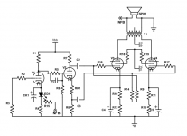
Maybe something close to this circuit, from this thread-
Classic 4 valve PPP circuits
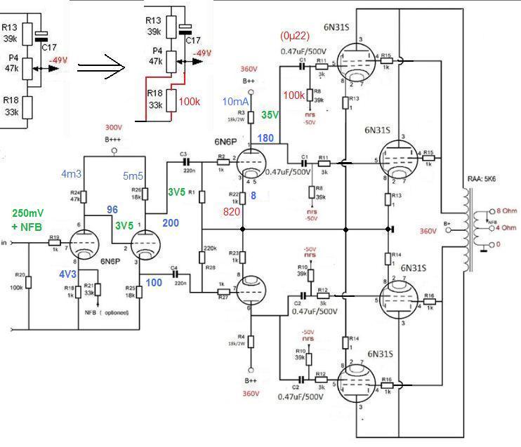
6SN7, 6CG7, 6N1P could work in the front ends here pretty well.
I'm very interested in helping design a group-blessed and approved project, but I can't guarantee anything. Feel free to use this thread for brainstorming, and I'll try to be more active in input
Anything you have seen me post or share is open to use in anything you wish to put together, I claim no specific rights to anything, as there is nothing new under the sun for the most part My project are always for fun and are shared so that anyone finding it interesting can build it too
I have been planning a build using the 12AV5GA as outputs for quite some time. I think a driver PCB that is meant to be more universal with different outputs wired on off-PCB sockets would be very versatile. Any topology in mind? I think something like this could easily use the EL36, 6AV5GA, or even regular audio types on the outputs.
Feel free to post your design goals and desired attributes, here, and let's see what sounds good to you
For instance-
triode/pentode/UL?
desired supply voltage?
bias? fixed? cathode? other?
front end- concertina? differential? both? (concertina feeding a differential sounds great)
Something like a 100x100mm PCB with output bias, splitter, and driver all onboard with the outputs wired to separate sockets offboard would be very nice and handy.
I'm not terribly familiar with the EL36 so let me look at it and see what sounds like a good solution and operating points.
Well, just after a little bit of digging, I really like the EL36
Some interesting projects floating around, but the one that seems like a starting point to chop up for what I would want to build is the one by Patrick Turner-
2323-triode-integrated-6cm5
CCS-tail differential for nice balanced drive, some NFB, triode outputs, looks nice. Maybe go with a slightly higher gain tube up front to cut out that first stage (6N1P, perhaps?) or go with a concertina with that triode instead to drive both of the differential grids.
Hmmmm.
Maybe something close to this circuit, from this thread-
Classic 4 valve PPP circuits
6SN7, 6CG7, 6N1P could work in the front ends here pretty well.
Attachments
- Status
- This old topic is closed. If you want to reopen this topic, contact a moderator using the "Report Post" button.
- Home
- Amplifiers
- Tubes / Valves
- 6N2P/6CW5 design with toroidal outputs