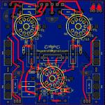
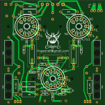
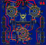
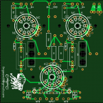
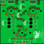
Alright, worked on moving as many signal traces to the top of the board as I could (based off of GoatGuy's suggestion in another thread, as always his advice makes sense, especially for the low-level signal at the input/splitter) and started cleaning things up a bit. Also added some extra clearance around the higher voltage pins and supply connections. Starting to look close to final.
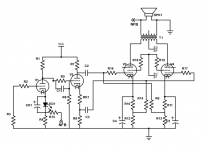
Thanks to Digi-key Scheme-it (thanks for the recommendation, Kodabmx!) I've got a presentable (if busy) schematic. This is not fully annotated with all the options (and I can't find a suitable outline for the LM317 in the listed library that isn't really funky) but is more or less complete, and the parts values should (emphasis on should) match the board as of now. As shown, it is set up for the "step network" bias that I like to use.
You may notice a similarity to my Flea Amplifier (along with John Broskies "Unexpectedly good" amp, and some of Morgan Jones' stuff too) and you are very right , as they are much the same with added features, and a swap to pentode outputs. The cathode circuitry looks redundant, and that's because it is, its all on the schematic to make the board easier to understand")
The board assumes an offboard power supply of your choice (my mosfet board would be useful here) however it features a basic CRC filter on board for the input/splitter stage to help out if needed, and has provision for two separate connections for two separate supply voltages to feed the input/splitter and output tubes separately if so desired.
Basically, the following options will be supported by the board-
For the input stage-
-Capacitor bypassed resistor, populate CK1, and a resistor will go in the LED1 postion, standing vertically, jumper out R4, leave R15 open, no global negative feedback
--Same as above, with added R4/R15 resistor combination for negative feedback
-LED bias, populate LED1 position, leave off the CK1 capacitor position, jumper out R4, leave R15 open, no global negative feedback
--Same as above, with added R4/R15 resistor combination for negative feedback
-Unbypassed cathode resistor, jumper out either CK1 or LED1, populate R4, do not populate R15 no global negative feedback
-Same as above, with added R15 for negative feedback (this is my preferred use!)
For the phase splitter-
-Direct coupled grid to preceding stage, populate RSB cathode resistor with wire link, do not populate C1 or R6. Install wire link (or small value grid stopper) for R5.
-Self biased or "floating" concertina, populate C1, RSB, R6, populate wire link LINK2 between R6 and RSB/R8 junction. Do not populate R5 or LINK1.
-Step-network bias, populate C1,R5,R6, install wire link in RSB position. Install wire link in LINK1 position. Do not populate LINK2. (this is my preferred use!)
For the output stage cathodes-
-Standard cathode bias, populate R10, R11, C4, C5. Install wire link in R12 and R13 positions. Do not populate LM317, or R_ADJ.
-Garter bias, populate R10, R11, R12, R14, C4, C5. Do not populate LM317, or R_ADJ. (this is my preferred use!)
-LM317 CCS cathode bias, populate C4, C5, LM317, and R_ADJ. Install wire link for R12, R13.
For the output stage screens-
-Triode mode, connect R18, R19 to the anode of the respective tube (additional pads are provided) rather than to the output connector. populate the output terminal with a 3POS terminal (or a 5POS for later experimentation)
-Ultralinear mode, populate R18, R19 as shown on the board. Populate output terminal block with 5POS terminal. Connect off-board as shown on chosen transformer wiring diagram.
-Pentode mode, Connect as above for ultralinear mode, and bring leads from output terminal to external (adjustable, if possible) power supply. (this is my preferred use!)
Thanks to Digi-key Scheme-it (thanks for the recommendation, Kodabmx!) I've got a presentable (if busy) schematic. This is not fully annotated with all the options (and I can't find a suitable outline for the LM317 in the listed library that isn't really funky) but is more or less complete, and the parts values should (emphasis on should) match the board as of now. As shown, it is set up for the "step network" bias that I like to use.
You may notice a similarity to my Flea Amplifier (along with John Broskies "Unexpectedly good" amp, and some of Morgan Jones' stuff too) and you are very right , as they are much the same with added features, and a swap to pentode outputs. The cathode circuitry looks redundant, and that's because it is, its all on the schematic to make the board easier to understand
The board assumes an offboard power supply of your choice (my mosfet board would be useful here
) however it features a basic CRC filter on board for the input/splitter stage to help out if needed, and has provision for two separate connections for two separate supply voltages to feed the input/splitter and output tubes separately if so desired.Basically, the following options will be supported by the board-
For the input stage-
-Capacitor bypassed resistor, populate CK1, and a resistor will go in the LED1 postion, standing vertically, jumper out R4, leave R15 open, no global negative feedback
--Same as above, with added R4/R15 resistor combination for negative feedback
-LED bias, populate LED1 position, leave off the CK1 capacitor position, jumper out R4, leave R15 open, no global negative feedback
--Same as above, with added R4/R15 resistor combination for negative feedback
-Unbypassed cathode resistor, jumper out either CK1 or LED1, populate R4, do not populate R15 no global negative feedback
-Same as above, with added R15 for negative feedback (this is my preferred use!)
For the phase splitter-
-Direct coupled grid to preceding stage, populate RSB cathode resistor with wire link, do not populate C1 or R6. Install wire link (or small value grid stopper) for R5.
-Self biased or "floating" concertina, populate C1, RSB, R6, populate wire link LINK2 between R6 and RSB/R8 junction. Do not populate R5 or LINK1.
-Step-network bias, populate C1,R5,R6, install wire link in RSB position. Install wire link in LINK1 position. Do not populate LINK2. (this is my preferred use!)
For the output stage cathodes-
-Standard cathode bias, populate R10, R11, C4, C5. Install wire link in R12 and R13 positions. Do not populate LM317, or R_ADJ.
-Garter bias, populate R10, R11, R12, R14, C4, C5. Do not populate LM317, or R_ADJ. (this is my preferred use!)
-LM317 CCS cathode bias, populate C4, C5, LM317, and R_ADJ. Install wire link for R12, R13.
For the output stage screens-
-Triode mode, connect R18, R19 to the anode of the respective tube (additional pads are provided) rather than to the output connector. populate the output terminal with a 3POS terminal (or a 5POS for later experimentation)
-Ultralinear mode, populate R18, R19 as shown on the board. Populate output terminal block with 5POS terminal. Connect off-board as shown on chosen transformer wiring diagram.
-Pentode mode, Connect as above for ultralinear mode, and bring leads from output terminal to external (adjustable, if possible) power supply. (this is my preferred use!)
Attachments
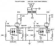
I wanted to go for an all-noval design this time, so went with the wonderful and affordable 6N2P for the front end, and went with rather boring but effective values to set it up.
I am following your progress with great interest. Especialy like your approach to enable multiple heater voltages. One question - do you actually need the amplification factor of a 6n2p in the first tube? I am interested in trying other tubes in that position also.
Well, I like it there to give headroom for global feedback, and the cathode is not bypassed in order to increase linearity with the side effect of lowering overall gain. At my operating point each grid needs 16 volts peak for full output, but if going without global feedback and either bypassing the resistor or using an LED and running something like the EL84 with lower drive requirements you can easily use the 6N1P, 6DJ8, 12AT7, or even a 6CG7 if your source is hot enough. That's one of the main reasons that I'm working different options to the PCB, to give the ability to make something very nice with many different possible tube types one may have on hand.
If I'm not mistaken the 6N2P gives a gain of ~60 or so the way I've implemented it.
In particular, I have two ideas I would like to build-
EL84 triode connected version with a 6CG7 front end, likely with LED bias and no overall negative feedback. Should be nice for hot sources and efficient speakers
6P43P-E triode connected, with 6N1P front end, a smidge of global feedback, overall supply voltage of ~250 volts, should be good for 7~8 watts or so.
I also build a bunch of regulated G2 pentode connected or UL mode EL84 builds from time to time, so that's also a need for this board. Being able to accommodate a customer's needs/requirements with a single board is handy when you build a bunch each year.
Well, I figured this board needs a name. So, while trying to fall asleep last night, thinking myself into a stupor, the name "Spider" came to me. I feel it fits the idea of the board, many legs and possibilities, so, "Spider" it is. It fits the theme with the Flea amplifier I think.
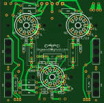
The Spider logo silkscreened to the PCB is from Openclipart.org, and has an unlimited public/commercial use license.
I'm thinking of including a feedback capacitor on the board, but just unsure of what lead spacing to use. There seem to be plenty of quality film caps in the pF range with 5mm lead spacing, so I think that's what I'll do, unless there are any other suggestions. I'll likely incorporate this into the noval SE flea board as well.
If I'm not mistaken the 6N2P gives a gain of ~60 or so the way I've implemented it.
In particular, I have two ideas I would like to build-
EL84 triode connected version with a 6CG7 front end, likely with LED bias and no overall negative feedback. Should be nice for hot sources and efficient speakers
6P43P-E triode connected, with 6N1P front end, a smidge of global feedback, overall supply voltage of ~250 volts, should be good for 7~8 watts or so.
I also build a bunch of regulated G2 pentode connected or UL mode EL84 builds from time to time, so that's also a need for this board. Being able to accommodate a customer's needs/requirements with a single board is handy when you build a bunch each year.
Well, I figured this board needs a name. So, while trying to fall asleep last night, thinking myself into a stupor, the name "Spider" came to me. I feel it fits the idea of the board, many legs and possibilities, so, "Spider" it is. It fits the theme with the Flea amplifier I think.
The Spider logo silkscreened to the PCB is from Openclipart.org, and has an unlimited public/commercial use license.
I'm thinking of including a feedback capacitor on the board, but just unsure of what lead spacing to use. There seem to be plenty of quality film caps in the pF range with 5mm lead spacing, so I think that's what I'll do, unless there are any other suggestions. I'll likely incorporate this into the noval SE flea board as well.
Attachments
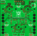
As shown there are M3 mounting holes on either side of each socket currently, in order to work with 12mm/1/2" standoffs or spacers... I placed them near to the sockets to reduce strain for those that may wish to swap tubes frequently. Are you suggesting a set of additional holes? I avoided them in the outside corners to reduce board flex and fatigue of solder joints at the sockets.
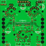
To keep in line with the SE board, I added a feedback compensation cap outline, assuming a 5mm box MKS type or similar. Otherwise I think it's done.
To keep in line with the SE board, I added a feedback compensation cap outline, assuming a 5mm box MKS type or similar. Otherwise I think it's done.
Attachments
Thanks for your interesting work on exploring the EL86. I was particularly interested to hear you thought it sounded like a EL84 with more mojo. I’m planning to build this amp in the near future, so I hope you find time to get the PCB fixed up for the fans. Meanwhile I’m beginning to search my closet for a suitable power transformer.
You wrote in post #1 “For power, an Antek AS-1T230 - 100VA toroid gets rectified through a 1N4007 bridge, fed to a pair of IRF820 mosfet filters, one of which uses a string of five 1N5262 50 volt zeners, with a pot/resistor in series feedig the mosfet gate for adjustment range. This gives an effective way of setting the screen voltage. The output tubes get their plate supply straight from the first reservoir cap, and the additional unregulated but smoothed mosfet filter feeds the preamp stage.”
So you are running a B+ of around 320VDC, which puts about 300V across the EL86. What do you get for screen and front-end voltages? Have you cranked up the dissipation yet above 10 watts? What current and dissipation are you getting now?
It would be helpful if you update the schematics with this information as well as the power transformer info. Have you perhaps done power and distortion measurements?
Regarding Va of 300 VDC - have you experimented with other voltages and operating conditions and found this best? The data sheets seem to indicate 250 VDC. Your comments shall be appreciated.
The board design looks good, and I like the flexibilty to easily use different heater voltages for the power and voltage amp tubes, without board surgery. (I happen to have a bunch of PL84 tubes (oddly numbered EL86s with 15 V heaters).
One suggestion, since you have plenty of space, is to allow for physically larger coupling capacitors (like fat Clarity Caps), and move them away a bit from the big (hot) cathode resistors.
You wrote in post #1 “For power, an Antek AS-1T230 - 100VA toroid gets rectified through a 1N4007 bridge, fed to a pair of IRF820 mosfet filters, one of which uses a string of five 1N5262 50 volt zeners, with a pot/resistor in series feedig the mosfet gate for adjustment range. This gives an effective way of setting the screen voltage. The output tubes get their plate supply straight from the first reservoir cap, and the additional unregulated but smoothed mosfet filter feeds the preamp stage.”
So you are running a B+ of around 320VDC, which puts about 300V across the EL86. What do you get for screen and front-end voltages? Have you cranked up the dissipation yet above 10 watts? What current and dissipation are you getting now?
It would be helpful if you update the schematics with this information as well as the power transformer info. Have you perhaps done power and distortion measurements?
Regarding Va of 300 VDC - have you experimented with other voltages and operating conditions and found this best? The data sheets seem to indicate 250 VDC. Your comments shall be appreciated.
To keep in line with the SE board, I added a feedback compensation cap outline, assuming a 5mm box MKS type or similar. Otherwise I think it's done.
The board design looks good, and I like the flexibilty to easily use different heater voltages for the power and voltage amp tubes, without board surgery. (I happen to have a bunch of PL84 tubes (oddly numbered EL86s with 15 V heaters).
One suggestion, since you have plenty of space, is to allow for physically larger coupling capacitors (like fat Clarity Caps), and move them away a bit from the big (hot) cathode resistors.
Screen voltage is about ~225, plate voltage about ~310, cathode voltage ~32 (across both garter bias resistors, so 16 volts x2) so actual operating parameters are close to 190 screen, 280 plate actual, -16 g1. Not too far off, and you get a little more potential power with a smidge lower (in theory) distortion. You could run them hotter at idle but I see no need to, I like them to last and have efficient speakers that are happy with a smaller class A area.
I've noticed these really don't like the screen voltage to be too high once you run the plate higher- they will get towards red plate territory above 300 volts screen, even if you run the grid quite negative.
Also- the Russian 6P43P-E doesn't like these points either, it wants twice the negative bias and maybe ~70% of the same screen voltage, unless you bring the plate voltage below 280 or so. Otherwise very promising tube.
For the caps, get me lead spacing dimensions and I'll see about making a couple pads/holes to mount them, it shouldn't be too tricky to pull a couple traces further out... The assumption is that the caps will be under the board, and the bigger resistors would be on top, so I don't think heat will be too much of a concern in most instances. I haven't played with them boards much lately, but I think they are nearly done.
Last edited:
Screen voltage is about ~225, plate voltage about ~310, cathode voltage ~32 (across both garter bias resistors, so 16 volts x2) so actual operating parameters are close to 190 screen, 280 plate actual, -16 g1.
<snip><snip>
For the caps, get me lead spacing dimensions and I'll see about making a couple pads/holes to mount them, it shouldn't be too tricky to pull a couple traces further out... The assumption is that the caps will be under the board, and the bigger resistors would be on top, so I don't think heat will be too much of a concern in most instances. I haven't played with them boards much lately, but I think they are nearly done.
Thanks for the approximate HV targets. I think my stash will provide.
Regarding lead spacings; I don’t have any specific coupling caps in mind, so just provide multiple options as much as your PC board real estate could accomodate. I have some great Jantzen Superior Z caps that measure 17x43 mm. I will build your amp using those after convincing myself it could benefit from high quality parts.
That makes me wonder - what output transformer impedance would make this amp really sing at the stated HV supply?
Pardon the terrible picture and sloppy schematics!
Lingwendil,
As I’m getting ready to build a 6CW5 PP amp I would like to learn a bit more from your experience with your amp. Since your PCB is not out yet
I have a Baby Huey PCB that I plan to use, but will look at your design for operating point and screen and B+. The difference is that the Baby Huey has fixed bias, so I need to adjust my power supply accordingly.Your amp has about 280-290V across the tube vs. the spec sheet max of 250V. Any concerns after using the amp for a while? How many hours have your tubes survived so far? Perhaps the secret is that your plate dissipation is well below the 12 watts max.
My main question. I understood 6CW5s “like lower voltages and higher currents”, so I wondered why you chose this operating point. Would you pick a different point if your were doing it again?
How about making a nice, “unsloppy” schematic for us
. There are some numbers that are hard to read and missing some.Any progress on the nice PC board you had designed?
Sorry, I'm still alive, yes I've been pretty busy and haven't been able to do much in the way of audio projects for a while unless it's on a computer... other than some various PCB design (not all of which is audio related) I haven't been able to work on anything other than an aquarium LED driver PCB.
For some reason I'm not getting topic reply notifications
For output transformer, I think that anything from 3000-4000 ohms would do fine, with slightly lower distortion at the higher impedance, and slightly higher power with the lower.
In my situation I have no issue at all with violating the max plate voltage due to the low idle current. I find with the low average power output that I need this gives fantastic headroom, while increasing the useful life of the tubes. Other than tube rolling to test new purchases for a day or so at a time, I still run the original Polam tubes I first settled on, and the bias voltage still measures within a few dozen millivolts, and that's with a good ten or twelve hours a day usage. If we are home and awake, the amp is on. I recently moved it into the garage to use primarily on weekends while finishing other projects, and family uses it all day practically as well.
I wouldn't hesitate to build it with lower supply voltage if I had the right stuff on hand and run a higher idle dissipation to suit. Power output would go down, but I think it wouldn't make much difference otherwise. I tend to prefer to run around 230-240 volts AC before rectifying for most tube projects, as it's a common and easy transformer secondary voltage to find, even with non tube-specific suppliers.
PCB design is pretty much done, I want to have some made and tested before I declare it "done" enough to give out files (or sell boards) for now. I actually think I may do a PCB order this next week, as I have several designs ready to order, more or less. I need to redraw the schematic, too, my handwriting sucks
Any other questions or suggestions let me know, I'm going to try and be more active here again, I have several projects that really need finished
I've been pretty busy and haven't been able to do much in the way of audio projects for a while unless it's on a computer... other than some various PCB design (not all of which is audio related) I haven't been able to work on anything other than an aquarium LED driver PCB.For some reason I'm not getting topic reply notifications
For output transformer, I think that anything from 3000-4000 ohms would do fine, with slightly lower distortion at the higher impedance, and slightly higher power with the lower.
In my situation I have no issue at all with violating the max plate voltage due to the low idle current. I find with the low average power output that I need this gives fantastic headroom, while increasing the useful life of the tubes. Other than tube rolling to test new purchases for a day or so at a time, I still run the original Polam tubes I first settled on, and the bias voltage still measures within a few dozen millivolts, and that's with a good ten or twelve hours a day usage. If we are home and awake, the amp is on. I recently moved it into the garage to use primarily on weekends while finishing other projects, and family uses it all day practically as well.
I wouldn't hesitate to build it with lower supply voltage if I had the right stuff on hand and run a higher idle dissipation to suit. Power output would go down, but I think it wouldn't make much difference otherwise. I tend to prefer to run around 230-240 volts AC before rectifying for most tube projects, as it's a common and easy transformer secondary voltage to find, even with non tube-specific suppliers.
PCB design is pretty much done, I want to have some made and tested before I declare it "done" enough to give out files (or sell boards) for now. I actually think I may do a PCB order this next week, as I have several designs ready to order, more or less. I need to redraw the schematic, too, my handwriting sucks
Any other questions or suggestions let me know, I'm going to try and be more active here again, I have several projects that really need finished
Lingwendil,
Thanks for the answered questions and your update on the 6n4p/6CW5 PCBs. I will proceed with a EL86 version of the Baby Huey design using your operating point adjusted for my OTs. I have a pair of Heyboer output transformers without Ul taps and with 3.4k plate to plate impedance which I will try. See here:
EL34 Baby Huey Amplifier
- Status
- This old topic is closed. If you want to reopen this topic, contact a moderator using the "Report Post" button.
- Home
- Amplifiers
- Tubes / Valves
- 6N2P/6CW5 design with toroidal outputs