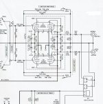
Hey guys I don't know much about tubes and their configurations, can some one look at this and tell me what it is. It's from a highly regarded Japanese preamp the gain is switchable from a 1 or 2 db to 20db.
Cheers George
I'm learning I think it's a CCDA????
Cheers George
I'm learning I think it's a CCDA????
Attachments
Last edited:
There is nothing in parallel.
It is a stereo (2 channel) preamp.
Each channel has a common cathode stage DC coupled to a cathode follower.
Each channel has negative feedback, and a switch to select different feedback resistors to give different gain according to the switch position.
It is a stereo (2 channel) preamp.
Each channel has a common cathode stage DC coupled to a cathode follower.
Each channel has negative feedback, and a switch to select different feedback resistors to give different gain according to the switch position.
It's a textbook configuration. Gain stage --> cathode follower. With feedback back to the input.Is it good/bad/ugly/indifferent What would the output impedance be ???
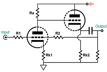
The output impedance will be approximately equal to 1/gm, divided by the feedback factor (which is switchable, so it depends on the setting). In other words, it will be very low, like a couple of hundred ohms.
In other words, it will be very low, like a couple of hundred ohms.[/QUOTE]
"couple of hundred ohms:" that's great I suppose the higher the gain the lower the output impedance?
And so long as I make C15 and C16 large enough it will stay constant of the audio band?
Just off the top, would this be very complicated to be moded into a paralleled cathode follower, as I read that's the lowest output impedance one can get from tube buffer?
Cheers George
Last edited:
Because output impedance is not the same as drive capability. With enough feedback you could make the output impedance vanishingly small, but that still doesn't mean a little 12AU7 could drive your loudspeakers!100kohm!! why so high, if the output impedance is only a couple hundred ohms?
40k isn't too bad in this case. You will get away with it.that means it's going to see a load of around 40kohms?
It is a simple circuit with average performance into a high impedance load, but poorer performance into a lower impedance load. Voltage gain will be switchable from 11dB to 2.2dB. Performance is limited by the choice of valve and the low supply rail voltage.georgehifi said:It's from a highly regarded Japanese preamp the gain is switchable from a 1 or 2 db to 20db.
martyh,
I am surprised by you suggestion that for the two circuits, post #1 and post #4 decreasing the load resistance will null the distortion.
Would you give us a discussion on how that works on one or both of those circuits, please. Either with, or without negative feedback. Also list what distortion(s) will be nulled; 2nd, 3rd Harmonic; 2nd, 3rd Intermod, etc.
I am guessing what you are taking about is that when you reduce the load resistance on the cathode follower that its 2nd harmonic distortion goes up; and that when the cathode follower's 2nd harmonic distortion is the same percent as the input stage 2nd harmonic distortion, they will null (since they are in opposite directions, one on positive alternation, and one on the negative alternation). Of course, now with both positive and negative alternations being fore-shortened, we have 3rd Harmonic distortion at a larger percent than we had before reducing the load resistance, right?
Last edited:
OK time to let the cat out of the bag, this is a new Japanese kit I've yet to put together, I did a swap for a Lightspeed Attenuator as I like having many different pres active and passive on hand to A/B's with at demos with the Lightspeed, for customers.
But I don't want to disadvantage it by it seeing a load that's too low for it, I've had a look and can raise my total load to 68kohm?
Doctorjohn Cheaptubeaudio: Audio Reviews and More: Review: Elekit TU-8500 Full-Function Preamp, Part I
Cheers George
But I don't want to disadvantage it by it seeing a load that's too low for it, I've had a look and can raise my total load to 68kohm?
Doctorjohn Cheaptubeaudio: Audio Reviews and More: Review: Elekit TU-8500 Full-Function Preamp, Part I
Cheers George
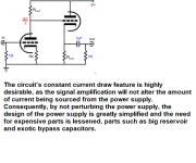
Found this on Tubecad looks to be a CCDA??
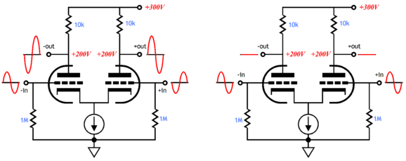
Not a diff amp, but it draws approx. constant supply current. "Constant Current Draw Amplifier" So does a typical tube differential amplifier.
Last edited:
I don't want to disadvantage it by it seeing a load that's too low for it, I've had
a look and can raise my total load to 68kohm?
That will work, but it's best for the load to be several times larger than the 33k cathode resistor.
Last edited:
The output impedance is small signal, but not suitable for driving a difficult load. If too small, the load will increase the distortion. As a rule of thumb, the load should be at least 3-5 times the cathode resistor, so 100k - 170k is preferable, but the higher the better, naturally.
Last edited:
The load (if too small) will increase distortion. As a rule of thumb, the load
should be 3-5 times the cathode resistor, so 100k - 170k is preferable.
Can the R48 R49 cathode resistor be reduced to something like 10kohms without cause other trouble and major re-jigging?
Like on Tube Cad John Broskie's CCDA: constant-current-draw amplifier
Cheers George
Last edited:
His circuit uses higher B+ (200V vs 140V). Try 20k first, that should work. The plate current will increase by the reciprocal factor, as the grid voltage is constant. Is the power supply just passive dropping resistors? One or more of those may have to be decreased.
The input section has low plate current, another limitation of this circuit.
The input section has low plate current, another limitation of this circuit.
Last edited:
- Status
- This old topic is closed. If you want to reopen this topic, contact a moderator using the "Report Post" button.
- Home
- Amplifiers
- Tubes / Valves
- Can someone give some info on this tube circuit please?