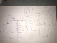
Can someone help me to calculate right RIAA values for the circuit attached? RIAA elements are in the circles on the drawing. I've used this calculator: AnyEQ: Equalization and after typing the capacitors values that are currently used, the following resistor recommendations appeared: 130k instead of 150k 14.5k instead of 15k. 72k instead of 47k.
Attachments
")
Calculation of the POLES is straight forward... You usually don't need to calculate the ZERO if your 2 POLES are properly placed.... since the ZERO will fall into place...
Here is the calculation for the first stage POLE...ie time constant ...
Make an equivalent R called Rz and Rzz..
Rp= Plate resistor=100K
Ra= Plate resistance at the operating condition = 56K assuming a 12AX7
R1 = 150K
R2= 15K
Rg= 510K
Rz = ((Rp//Ra) + R1) // Rg
Rzz= Rz+ R2
C1 = .022uF
1st Time Constant = Rzz * C1 = 3322us
Should be 3180us
Substituting in the updated vales you provided...
1st time constant = 3073us ....a little closer to 3180us
If you adjust R2 to 19.3K ...then you hit the time constant on target....
If interested we can review the second stage time constant.... what tube are you using ??
Last edited:
(C) Wakutoma, PL
1. For the first part should be
a) (Rout1 + R4) || R7 = ((Rout1 + R4) * R7) / (Rout1 + R4 + R7) = 9 * R5
where Rout1 is the first degree output that is approximately equal to Rp || R2 = Rp * R2 / (Rp + R2) assuming an infinite degree load
where Rp is the internal resistance of the lamp read from the card at a given work point.
In the case of a smaller value of the R4 resistor, the first stage will see a significantly lower load and then it must be included in the calculations or use the EccLab program (incl).
In this particular case 6072 goes out (add word - in calculations it is better to use the 12ay7 lamp card because it shows more voltage) I assume that Rk = 680R
about 2mA (a lot) at Va = 105V for B + = 300V
and 1.65mA at Va = 85V for B + = 250V (operating points depend on the adopted supply voltage for 1 stage I have installed 250V or 300V).
Hence
Rp (Rwew in ecclab) = 28K, Gm (Sa in ecclab) = 1.6mA / V and mu (Ka in ecclab) = 45 (for B + = 300V) and
Rp = 30K, Gm = 1.45mA / V and mu = 44 (for B + = 250V).
The reading is approximate because we have no value for Va = 100V only for 150V.
Assuming a load (Rs in ecclab) 150K for the first degree with EccLab we have
Rout1 = 19K1 (for B + = 300V) and 20K (for B + = 250V)
The difference is not so big (assuming an infinite load if, for example, DC is coming out 28K || 100K or about 21K9 / 23K1 for 300v / 250v). At the same time, 1 step gain is about 30 times.
Summing from the above formula (red at the very beginning) it should be (for example, for B + = 250V)
(20k + 150k) || 510k = 127k5 on one side and 9 * 15k = 135k on the other hand and so it is not exactly. To be more accurate, for example, increase R7 to 680K then the first part will give 170K || 680K = 136K or increase R4 to 163K6 (but of course this value is not in line) what will give 183K6 || 510K = 135K
b) R5 * C3 should give 318 in this case 15000 * 0.022 gives 330 so quite an approximation of about 4% but Nardi generally does not care about the accuracy in this system. To be exact, the C3 should be reduced to 21.2nf or R5 parallelized to 390K
2. For the second part should be (take into account the correction resulting from the addition of the 2M mesh leakage resistor 5687 - be careful because such a large resistor can add 5687 extra grid leak bias and change its work point)
((Rout_srpp + R10) || Rs) * (C6 + Cin_5687) = ((Rout_srpp + R10) * Rs / (Rout_srpp + R10 + Rs)) * (C6 + Cin_5687) = 75
where Rout_srpp is the output resistance of this unfortunate srpp. Without penetrating from ecclab it should be for Va = 300V and Rk = 2K2 (I = 0.75mA) about 26K7
and Cin_5687 is the input capacity of 5687 read from the Cin = card (Cag * mu + Cgk), ie about 4pf * 16 + 4pf = 68pf
To sum up, we have ((26K7 + 47K) || 2M) * (0.001 + 0.000068) = 71K1 * 0.001068 = 75k9 so it is approx. U Nardi was about 5% too much.
Last edited:

All I can say is that analysis is in disarray... It all over the place and not entirely correct..
When you set up your DC Gain level in the first stage , ie low frequency Gain limits, you set the voltage divider values then leave them be.... No need to touch them since these will affect distortion calculations that set them in the first place..... If you need to adjust the first time constant at 3180us, you do so by adjusting that 15K ...adjusting the cap will only lead to absurd non standard values.... more practical to adjust the 15K ...
The second stage is a SRPP with an output impedance of 360 Ohms ....... not sure where 26K7 comes from..??
Using the Miller capacitance to partly complete the 75us time constant does not provide any assurance or consistency .... With a SRPP output Z of 360 Ohms and using 72KOhm with ideal miller effect you time constant is at 74.58us
(360 + 72K) //2M = 69.833K
69.833K * (1nF + 68pF) = 74.58us
My previous post showed the first stage time constant to be 3180us with the updated values you provided...
By only adjusting that 15K to 19.3K ...then you get 3180us ...
So these two time constants are for the two POLES in the transfer function..
The 318us is a ZERO in the transfer function and will fall into place if your 2 POLES are properly placed...
Last edited:
Personally, this is the way I do it:
1. I use those time constant formulas to get reasonably good values.
2. I use LTSpice (or whatever decent simulation software you might have) to simulate the circuit. I try to get the BEST models possible.
3. I adjust the passive components to see what kind of impact they have. If small component value changes result in big changes in equalization, then I try for a different design.
4. Breadboard the design and use an inverse RIAA network to fine tune it (hint - lots of work here if you don't have the right tools already).
5. Compare it to my best efforts already... etc.
Sound tedious and complex? Yes it is. This is probably why you don't see many people posting their phono circuits, and why some phono circuits threads are so long, which so many iterations.
Again, srpp in phono? you really want to do that? I wouldn't but to each their own...
btw - nothing wrong with filling in a hole in a chassis, and using a proven circuit.
Calculation of the POLES is straight forward... <snip>
hi Cerrem
my first tube is 12AY7 aka 6072, second is SRPP 6SL7 and 5687 as last tube. Does your calculation require re-analysis due do 6072 in the input? Not sure if its important but for sure I will lower the operating point of the first tube, will leave 100k on anode, but increase cathode resistor to 1-1.5k.
If possible I prefer to keep the capacitors as they are currently. My 0.022 measure 0.021uf on precise multimeter. 1nf from second stage is 1nf.
All I can say is that analysis is in disarray... It all over the place and not entirely correct.. <snip>
Sorry to simplify the subject, but - Do I understand right that I should change 15k to 19.3k and 47k to 72k to get on the right spot?
I've made my own calculations based on the tube I use in 1st stage:
6072 output impedance 20kohm
20kohm + 150k resistor = 170k
170k || 680k rg = 136k
136k + 15k resistor = 151
151 * 0.021uf = 3171 us
So assuming that my capacitors (after careful measurment are 0.021uf) I should only change thr RG resistor to 680k (from 510k that is mounted currently)
6072 output impedance 20kohm
20kohm + 150k resistor = 170k
170k || 680k rg = 136k
136k + 15k resistor = 151
151 * 0.021uf = 3171 us
So assuming that my capacitors (after careful measurment are 0.021uf) I should only change thr RG resistor to 680k (from 510k that is mounted currently)
Are you sure SRPP of 6SL7 has an output impedance close to 360ohm? I am not the specialist, but I would say 20kohm minimum..The second stage is a SRPP with an output impedance of 360 Ohms
That looks correct...that would be the correct equation to use.... keep in mind I did not know what tube your were using when I first seen the schematic... When measuring caps for precision, I prefer to test them with a DC bias voltage on them, similar to what it will see in circuit... This first stage time constant is easiest to dial in when adjusting only 15K ...I've made my own calculations based on the tube I use in 1st stage: <snip>
I got confused since I thought you were using a 5687 for the SRPP...Are you sure SRPP of 6SL7 has an output impedance close to 360ohm? I am not the specialist, but I would say 20kohm minimum..
The SRPP Zout equation I use....
Zo= Rp(Rp+Rak) / 2Rp+(u+1)Rak
Thank you for your input Carrem, it's highly appreciated.
by the way - does anyone knows how to calculate 5687 output impedance in grid leak bias mode (cathode directly to ground)? Is the calculation much different than in regular amplification stage with cathode resistor capacitor bypassed?
by the way - does anyone knows how to calculate 5687 output impedance in grid leak bias mode (cathode directly to ground)? Is the calculation much different than in regular amplification stage with cathode resistor capacitor bypassed?
The 2nd (stacked) stage, in _my_ sim, shows output impedance near 3,700 Ohms.
Makes me wonder if "360 Ohms" is a slip of the slide-rule?
That is for 12AT7. 6SL7 will be somewhat different but not a lot.
It does NOT make sense to design the EQ to directly load-down a 3.7k node. The actual impedance is very variable with tube and tube-aging. And there is no reason to have such low impedances in this circuit. Pad-out the 2nd stage plate with 10X the estimated impedance; 39k or 47k. In fact I think this is what you intended, but drew it wrong.
I do not know why we would fret about "SRPP sound" when the final stage (carrying the biggest signal) is ZERO biased. This works good inside a NFB loop, or for low-level microphones, but is not a clean stable line-output stage when run naked.
What is the overall gain of this plan? Guessing stage 1 = 50, stage 2 = 40, stage 3 = 50(?), and RIAA has loss of 10:1 at 1KHz, gives 80dB, which is far too much.
Two high-Mu triode stages is usually all the gain a phono preamp needs. Why have three?
We want 1KHz gain near 100, and another 10:1 for 50Hz rise, total gain of 1,000.
Two high-Mu triode stages may be 30*30 which is about right.
Three stages works out like 10*10*10, BUT the 1st stage gain should be more-than-10 for good hiss performance through later stages. Say 20*7*7. It is difficult to get a small triode's gain as _low_ as 7 without spoiling its output impedance and hiss performance.
Two should be enough, three is plenty, but you already punched for four triodes, and have a plan, even though not polished or practical. The least-changes fix-up I see is the attached. The output stage should be wired as cathode follower. Tubes may be 6SL7, 12AX7, 12AT7, 12AY7, or other high-Mu types. While there will be differences of gain with various tubes, the RIAA EQ is well-swamped by Known Resistors and won't vary much with tube type. The last tube could profitably be a low-Mu like 6SN7.
Attachments
Hey soulmerchant, can you shed light on the SRPP distortion, and/or its sonic signature?
Thanks.
Well... some people like SRPP. I do like SRPP when it is optimized well. It is hard not to like it then.
Merlin Blencowe has noted on this very board that he has measured 0.01% THD for an optimised ECC88 SRPP driving a 15ohm load.
The problem is that it is far easier to optimize a differential stage than to optimize an SRPP stage though.
If the original poster is willing to take the time and effort, I would suggest that the SRPP might do better on the 1st stage.
My preference might be to use a Mu-follower on the 1st stage, differential amplifier, then cathode follower. And if it is for MM, I would however use a cascode on the 1st stage.
Last edited:
- Status
- This old topic is closed. If you want to reopen this topic, contact a moderator using the "Report Post" button.
- Home
- Amplifiers
- Tubes / Valves
- Need help with RIAA values/calculation