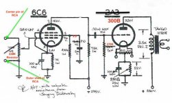
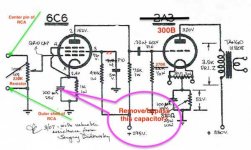
I have built this amp with the changes shown in Red. It sounds very good driven with a Cary 9SLP-98 into a pair of Heathkit AS-21. I do have a couple of questions hopefully someone here can answer.
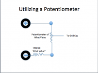
1) At the input RCA jack i have substituted a 220Kohm resistor for the 100Kohm pot. I was hoping to reduce the sensitivity of the amplifier as I can fairly move the volume control on the pre-amp Would changing back to the pot at 100K (or some other value) help in this regard? What is the purpose of the potentiometer at that point?
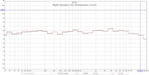
2) The output when measured with a RTA and pink noise shows a significant decrease above 10KHz. I've tried another pair of drivers that are supposed to play a little higher but the measurements are very similar. Any thoughts on changing cap values or something else to boost the top-end a bit?
This is my first foray into building off of a schematic so I appreciate and and all help and information.
Thanks
Dave
1) At the input RCA jack i have substituted a 220Kohm resistor for the 100Kohm pot. I was hoping to reduce the sensitivity of the amplifier as I can fairly move the volume control on the pre-amp Would changing back to the pot at 100K (or some other value) help in this regard? What is the purpose of the potentiometer at that point?
2) The output when measured with a RTA and pink noise shows a significant decrease above 10KHz. I've tried another pair of drivers that are supposed to play a little higher but the measurements are very similar. Any thoughts on changing cap values or something else to boost the top-end a bit?
This is my first foray into building off of a schematic so I appreciate and and all help and information.
Thanks
Dave
Attachments
Last edited:
At the input RCA jack i have substituted a 220Kohm resistor for the 100Kohm pot.
I was hoping to reduce the sensitivity of the amplifier as I can fairly move the volume
control on the pre-amp
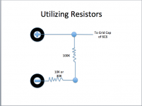
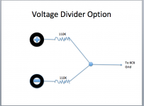
Just the one resistor won't change the sensitivity, you need a two resistor series/shunt attenuator.
Either the pot or the two resistors is ok, but don't go under 100k or there may be bass reduction.
With two resistors instead of the pot, to reduce the gain by about 20dB, use a series 100k
and a shunt 10k. If that's too much loss, try a series 100k and a shunt 30k.
Last edited:
This is my first foray into building off of a schematic so I appreciate and and all help and information.
Thanks
Dave
If you removed the cathode bypass cap on the 6c6 that would also reduce the amount of gain that the tube makes.
You may need to go a lot lower than 50%, even as low as single figures, before you notice treble boost. This technique is known as 'partial bypassing' - see reference below.
I recently built a similar amp off schematic. I found that the hum level increased when I removed the bypass capacitor!
You will still need the voltage divider, connected as shown in your post #6.
http://valvewizard.co.uk/ChoosingBypassCaps.pdf
I recently built a similar amp off schematic. I found that the hum level increased when I removed the bypass capacitor!
You will still need the voltage divider, connected as shown in your post #6.
http://valvewizard.co.uk/ChoosingBypassCaps.pdf
Yeah! I got lost after the first two paragraphs! Just wanted to show you the effect was real!
It's actually a filter effect. You really do have to use a small value capacitor. A 1uF provides boost above 1,000Hz for example - experiment with values on either side of 1uF and you might hear something. Film capacitors are good for this purpose.
It's actually a filter effect. You really do have to use a small value capacitor. A 1uF provides boost above 1,000Hz for example - experiment with values on either side of 1uF and you might hear something. Film capacitors are good for this purpose.

Maybe you should consider yourself fortunate that you're getting a flat response to 10kHz from such a simple circuit? Personally, I wouldn't be able hear much higher anyway! 
My suggestion of partial bypassing is unlikely produce the result you want. As DF96 says, you may have to look to other components in the circuit.
My suggestion of partial bypassing is unlikely produce the result you want. As DF96 says, you may have to look to other components in the circuit.
The 6C6 input stage in Pentode mode has a lot of gain, in the order of 600 or possibly more. You can change the circuit to triode mode and it will drop to a gain of 20. Remove the 2.2u cap and 470K resistor from pin 3. Place a 1K resistor from pin 3 to pin 2. Crank up the volume control on your pre-amp. Downside is you may not have enough gain from your pre-amp. You need about 104Vp-P drive to the 300B. Divide by 20 (mu in triode mode) and you need 5.2V p-p or 1.84Vrms drive from your pre-amp.
Are you using unusually long wires from the pentode plate to its plate resistor and the coupling cap, and from the coupling cap to the 300B grid resistor and grid? Are those wires placed/held in place tightly on the chassis, or are they bundled in a wiring harness with other wires? they should be 'floating' in air, and not tight or near to anything else (such as next to the 300B plate/tango 808 wire).
Is the 0.22uF cap in a metal enclosure, and is that metal mounted on, or contacting the chassis?
Are you using coax (shielded cable) from the coupling cap to the 300B grid resistor and grid?
Any of those items above would have unusually large capacitance loading on the pentode plate. That would reduce the high frequencies.
Last edited:
What load are you using when you are testing the frequency response of the amp (8 Ohm load resistor, or 4 Ohm as appropriate is good idea)?
Using a loudspeaker load is a bad idea to test the amp, but with care not to burn out the speakers, is a good idea to test the amp/loudspeaker as a system.
What test signal are you using to test frequency response?
What is the equipment that you are using to get the FFT? Are you using the audio in on some iPad or other brand pad? Are you using an external device connected to the pad; what model?
- Status
- This old topic is closed. If you want to reopen this topic, contact a moderator using the "Report Post" button.
- Home
- Amplifiers
- Tubes / Valves
- Radiotron SE Question