The grid wire is about 7 inches long. Twisted pair in a braided shielded configuration. Only 1 wire is connected at each end. Braid is grounded to chassis.
They are floating with the connections just 0.5 inches from entry point into chassis.
No cap is metal and they are either floating or mounted on plastic brackets.
No coax anywhere. Only shielded wire is the grid lead.
Thanks for your interest. I'll look at those things again.
They are floating with the connections just 0.5 inches from entry point into chassis.
No cap is metal and they are either floating or mounted on plastic brackets.
No coax anywhere. Only shielded wire is the grid lead.
Thanks for your interest. I'll look at those things again.
Are you talking about the Pentode grid wire? I was talking about the 300B grid wire.
But if you have a braided shield for the wire to the pentode grid, I understand. An unshielded wire can pick up hum. You use a shield wire and ground the braid, and the hum goes away.
But that increases the capacitance the 100k volume control has to drive. Depending on the capacitance of that shielded wire, the high frequencies could be attenuated, and by how much depends on where the volume control is adjusted.
That pot is a volume control. If you just want to reduce the input sensitivity, first figure out by how much, then make a voltage divider.
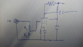
I drew a simple schematic for you
For example, if you want to attenuate the signal by 50%, make R1=R2=50k, and then the voltage will be 0.5 at the input of the tube, if it's 1V at the output of your preamp.
It doesn't really matter that the values add up to exactly 100k, so long as both channels are the same. I would aim for R1+R2 = between 100k and 200k.
The voltage at the input to the tube, will be Vg1 = VIN*(R2/(R1+R2) )
Attachments
I'll try that too. The reason I wanted a pot is that one of me ears is down a few decibels and thought I could use it as a balance control of sorts.
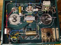
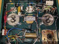
I'm attaching pics of the amps just in case someone notices something amiss.
Thanks
Dave
I'm attaching pics of the amps just in case someone notices something amiss.
Thanks
Dave
Attachments
if you want better high frequency response.....
increase the plate current of the driver tube...
by decreasing the cathode resistor or decreasing the resistor to the screens...
bear in mind that doing so decreases plate voltage,
so your plate swing is lower...
you can decrease the plate load resistor and this will lower the gain a bit but gives more plate swing...
this is an exciting thing, lots you can do, but do it in baby steps....
I'll try that too. The reason I wanted a pot is that one of me ears is down a few decibels and thought I could use it as a balance control of sorts.
I'm attaching pics of the amps just in case someone notices something amiss.
Thanks
Dave
Those are great looking amps! Just get some mono pots then, that's easy enough to do.. The pot works exactly like what I drew, you just get to pick the values of the resistors by turning the knob.
I can't see anything obvious which would raise the input capacitance of the 300B. Elsewhere I have seen estimates of 70-80pF as the typical input capacitance of 300B, which would give an HF rolloff around 25kHz. However, two rolloffs around 20kHz can give you something looking rather like a 10kHz rolloff so maybe it is capacitance plus OPT issues?
What load are you using when you are testing the frequency response of the amp (8 Ohm load resistor, or 4 Ohm as appropriate is good idea)?
Using a loudspeaker load is a bad idea to test the amp, but with care not to burn out the speakers, is a good idea to test the amp/loudspeaker as a system.
What test signal are you using to test frequency response?
What is the equipment that you are using to get the FFT? Are you using the audio in on some iPad or other brand pad? Are you using an external device connected to the pad; what model?
diyAudio Member
WntrMute2's Avatar
Join Date: Jan 2010
I am using 2 different things for testing. 1) REW RTA with external microphone and calibration code entered in software.
I also occasionally use 2) an iPad with RTA software - internal microphone.
While different of course, the two curves show similar drop off > 10KHz.
I am using pink noise via a CD player.
Pink noise rolls off at 3 dB per octave.
There is 3 dB less power from 10kHz to 20kHz than there is from 5kHz to 10kHz.
That is the nature of the signal you are using.
Using a Microphone and a loudspeaker to test the response of an amplifier
gives you an average of the response of the microphone, amp, and speaker
in the exact setup in the room you are in, distance to reflective and absorptive objects,
reflection from the microphone back to the speaker, etc.
But testing by using what you have for equipment and signal is creative.
Don't worry any more about the frequency response of your amplifier.
It probably is no more than -1 dB or -2 dB less at 40Hz (or lower), and at 20kHz; than it is at 1kHz.
(+0dB, -2dB from 40Hz (or less) to more than 20kHz).
Last edited:
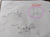
I've sketched a couple of circuits. The current one is on the right. I strapped the hot side of the RCA to ground through the 220K ohm as suggested by Min Yang.
My two proposed circuits are on the left. Proposed circuit 1 duplicates the current circuit but allows for adjusting the resistance to ground. Circuit 2 seems like it should be a voltage divider. Opinions on which I should use? Also should I put a resistor in series so the resistance doesn't end up being zero?
My two proposed circuits are on the left. Proposed circuit 1 duplicates the current circuit but allows for adjusting the resistance to ground. Circuit 2 seems like it should be a voltage divider. Opinions on which I should use? Also should I put a resistor in series so the resistance doesn't end up being zero?
Attachments
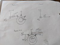
Circuit 2 is a volume control.
Opinions on whether passing the grid current through a pot or resistor will degrade the sound versus what is in there currently?
BTW, what's the name of the topology circled when used on a 6C6?
Thanks for all the help!
Dave
Attachments
^ it is always a good practice not to leave one side of an input cap hanging without anything connected to it like in an input of an amp, that resistor to the rca jack is a ground terminating resistor, a must have....it ensures that the cap does not accumulate charge or pick up rf signals and noise...than if left hanging...
the same goes for the output cap as well...
the same goes for the output cap as well...
- Status
- This old topic is closed. If you want to reopen this topic, contact a moderator using the "Report Post" button.
- Home
- Amplifiers
- Tubes / Valves
- Radiotron SE Question