I have already designed and built the output stage for a 13E1 single ended tetrode amplifier, linearised with a 13% cathode feedback output transformer. This produces full output with a little over 50VRMS of drive. I am using fixed bias applied by a DC servo in the form of the Broskie autobias, the input impedance of the output stage is 33K. B+ going into the output stage is 520V, so I have lots of volts to play with in the driver. I am planning on 13dB or so of GNFB so I need an open loop gain of about 200.
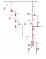
I have built a Bartola style hybrid mu follower, as shown in the graphic, based on a 6BX7. This drives the 50VRMS @ 2kHz into 33K at less than 0.7% THD, with most of that 2nd harmonic (3rd harmonic is -70dB) - in fact at 100VRMS distortion is still only 1.2%. the stage is -3dB at abvout 6Hz and 600kHz. I have a gain of 10 from this stage, so my plan was to used a first stage of a 6CG7 to give a total gain of about 200.
I have a plan to use two direct coupled stages of hybrid mu follower - with the 6CG7 anode fixed at about 110V, and the 6BX7 at 330V. I can use the constant curent source with a two stage resistor ladder to generate the two reference voltages for the two hybrid mu followers.
I have tested the 6CG7 stage, and for the 5VRMS required to drive the BX7 to full output the distortion is <0.1%.
The only thing I have not done is to direct couple the two and test the composite driver.
Is this a good plan? I am worried about having a lot of LF poles close together in the overall amp design and ending up with LF instability - at the moment I have the autobias (0.1Hz), 2 mu followers (currently 6Hz), the OPT (15Hz) and the coupling capacitor to the output stage (TBA).
Then there is the question of the voltage requirement for the hybrid mu stage capacitors - I thought about making the mu stage capacitors very large (to get the LF poles of the mu stages down below 1Hz), and that this would be easy and not expensive because as far as I can see the mu stage capacitors have 10s of volts on them in normal operation. So I was thinking of running with the mu capacitors at several microfarads. Can I do this and do I have the voltage requirement right?
I am very grateful for any received wisdom!
Attachments
I was thinking of running with the mu capacitors at several microfarads.
Can I do this and do I have the voltage requirement right?
Looks ok, remember the capacitor is more or less connected across the gate-source of Q3,
which is limited to 20V. Maybe use a plate fuse in case of the tube shorting.
Last edited:
I do not see what Q2 Q1 do for you. They feed a (fixed?) voltage to a 5.6Meg gate resistor. Even if it "improves PSRR", surely you can do that with an R and a C? And isn't the natural bias "half the supply", not some fixed voltage?
Not that they do any harm. But it is a few more bucks and a lot of extra work for no real benefit. Over-complication.
Not that they do any harm. But it is a few more bucks and a lot of extra work for no real benefit. Over-complication.
To Xpersephone2, and also in regard to the most recent poster;
I can see a constant current source with Q1, Q2. This will provide a constant voltage reference at the top of R4, increase PSRR and IMO you should keep this.
R5 and C1 will set the LF limit for the stage (as drawn) 5M6 and 0.22uF is -3db at ~0.14Hz. You should be able to increase 5M6 to 12M without penalty, and then use a high quality silvered mica capacitor in the pF range to set the LF of the stage (as drawn).
See if you can direct couple this to the next stage, and remove an additional LF pole !!.
Cheers, Hanze
Last edited:
Hybrid stage built and measured ...
'Hanze: R5 and C1 will set the LF limit for the stage (as drawn) 5M6 and 0.22uF is -3db at ~0.14Hz' - I thought this at first until; until I measured the response. It is -3dB at 2.5Hz for the 6BX7 stage as originally drawn. I have not calculated this but guess it is because the bootstrap C1 is driven from the Rp of the 6BX7 which is about 1200R.
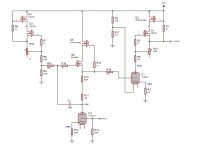
I decided there was no point in a second mu stage and a CCS performed as well - that has produced the two stage driver shown, which has a gain of 210. The production version will have a 47K dropper in the drain of Q5, so this is now protected against shorts of U1 or U2.
Performance is excellent - 0.2% THD at 50V RMS 2kHz, only increasing to 0.4% at 100VRMS. HF rolls off at about -3dB at 40kHz, I am not trying to improve this as to a first approximation that's about where I'd want to roll it off anyway. The LF pole is at 4Hz, I will increase C1 R10 (as drawn) in the final version.
'Hanze: R5 and C1 will set the LF limit for the stage (as drawn) 5M6 and 0.22uF is -3db at ~0.14Hz' - I thought this at first until; until I measured the response. It is -3dB at 2.5Hz for the 6BX7 stage as originally drawn. I have not calculated this but guess it is because the bootstrap C1 is driven from the Rp of the 6BX7 which is about 1200R.
I decided there was no point in a second mu stage and a CCS performed as well - that has produced the two stage driver shown, which has a gain of 210. The production version will have a 47K dropper in the drain of Q5, so this is now protected against shorts of U1 or U2.
Performance is excellent - 0.2% THD at 50V RMS 2kHz, only increasing to 0.4% at 100VRMS. HF rolls off at about -3dB at 40kHz, I am not trying to improve this as to a first approximation that's about where I'd want to roll it off anyway. The LF pole is at 4Hz, I will increase C1 R10 (as drawn) in the final version.
Attachments

- Status
- This old topic is closed. If you want to reopen this topic, contact a moderator using the "Report Post" button.
- Home
- Amplifiers
- Tubes / Valves
- Hybrid Mu Follower Questions - Driver stage for 13E1 Amplifier