Hey all!
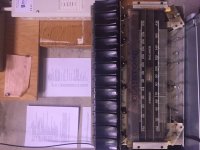
I inherited my grandparents old Clairtone S-401 (Princess) model. They bought it brand new in the early sixties. It was manufactured in March 1962. I have fond memories of playing records on it when I was a kid in the 80's/90's so there is some sentimental attachment to it.
The cabinet is in great shape as well as the turntable; however, I do not have much use for the full size console unit. I thought it would make a neat project to restore the amplifier portion and if it sounds good, I would create an enclosure for it and use it as a "Hi Fi" amp for home/office. Otherwise I would put it back in the console and figure out what to do with it then.
From what I have read, these were the better console units available at the time; therefore, I am hoping the amplifier has some potential to be great sounding.
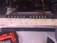
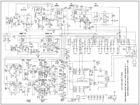
I have attached photos and the schematic for the amplifier. My plan is to replace all electrolytic capacitors, maybe upgrade the coupling capacitors, re-align the AM/FM receiver, and possibly modify some of the circuitry. I have powered the unit up with a variac and the amplifier does work but I cannot get sound from the radio.
After looking at the schematics, the first thing that popped out at me was the half wave rectifier for the tubes B+. I think modifying it to a full bridge rectifier would improve the power supply immensely. Any concerns doing this? Another thing is I don't see any specific phono RIAA section. Looks like all the inputs use the same pre-amp stage on tone control circuit? Also, the output transformers look a little small for to produce low frequency audio.
I would appreciate any ideas on how to modify it and if it really is worth putting a ton of time into it. I could just do the basic capacitor changes and leave it as is.
Thank you!
I inherited my grandparents old Clairtone S-401 (Princess) model. They bought it brand new in the early sixties. It was manufactured in March 1962. I have fond memories of playing records on it when I was a kid in the 80's/90's so there is some sentimental attachment to it.
The cabinet is in great shape as well as the turntable; however, I do not have much use for the full size console unit. I thought it would make a neat project to restore the amplifier portion and if it sounds good, I would create an enclosure for it and use it as a "Hi Fi" amp for home/office. Otherwise I would put it back in the console and figure out what to do with it then.
From what I have read, these were the better console units available at the time; therefore, I am hoping the amplifier has some potential to be great sounding.
I have attached photos and the schematic for the amplifier. My plan is to replace all electrolytic capacitors, maybe upgrade the coupling capacitors, re-align the AM/FM receiver, and possibly modify some of the circuitry. I have powered the unit up with a variac and the amplifier does work but I cannot get sound from the radio.
After looking at the schematics, the first thing that popped out at me was the half wave rectifier for the tubes B+. I think modifying it to a full bridge rectifier would improve the power supply immensely. Any concerns doing this? Another thing is I don't see any specific phono RIAA section. Looks like all the inputs use the same pre-amp stage on tone control circuit? Also, the output transformers look a little small for to produce low frequency audio.
I would appreciate any ideas on how to modify it and if it really is worth putting a ton of time into it. I could just do the basic capacitor changes and leave it as is.
Thank you!
Attachments
1. I thought it would make a neat project to restore the amplifier portion and if it sounds good, I would create an enclosure for it and use it as a "Hi Fi" amp for home/office.
2. After looking at the schematics, the first thing that popped out at me was the half wave rectifier for the tubes B+. I think modifying it to a full bridge rectifier would improve the power supply immensely. Any concerns doing this?
3. Another thing is I don't see any specific phono RIAA section. Looks like all the inputs use the same pre-amp stage on tone control circuit?
4. Also, the output transformers look a little small for to produce low frequency audio.
1. This is a Push-Pull 6L6 like design. Should produce wonderful sounds.
2. Agree in changing it to full wave rectifier. The "under load" Vht might be a bit higher after the change so you might have to adjust the output tube bias.
3. If it didn't use a magnetic phone cartiage, it didn't need RIAA
4. At 140V plate, it will yield 3W or so. You won't need a big output transformer.
Thank you Alllensoncanon for the reply.
That's great to know. Can't wait to hear it once I am done.
I will go ahead and do this. Probably will change the capacitors first, take some measurements then change to bridge rectifier. I will adjust the tube bias accordingly.
I wasn't aware of this. After a quick web search, it looks like ceramic cartridges are constant amplitude devices and don't need RIAA. You learn something new everyday!
This is good to know. I am planning on building some large full range speakers, so it may pair well with those. I guess listening will tell.
1. This is a Push-Pull 6L6 like design. Should produce wonderful sounds.
That's great to know. Can't wait to hear it once I am done.
2. Agree in changing it to full wave rectifier. The "under load" Vht might be a bit higher after the change so you might have to adjust the output tube bias.
I will go ahead and do this. Probably will change the capacitors first, take some measurements then change to bridge rectifier. I will adjust the tube bias accordingly.
3. If it didn't use a magnetic phone cartiage, it didn't need RIAA
I wasn't aware of this. After a quick web search, it looks like ceramic cartridges are constant amplitude devices and don't need RIAA. You learn something new everyday!
4. At 140V plate, it will yield 3W or so. You won't need a big output transformer.
This is good to know. I am planning on building some large full range speakers, so it may pair well with those. I guess listening will tell.
This is good to know. I am planning on building some large full range speakers, so it may pair well with those. .
You might want to measure the speaker impedance before hand if the output transformer doesn't have multiple speaker taps.
Almost all piezoelectric cartridges damage records.  The cart. and TT should be carefully examined and likely replaced. If minimum fuss with a mag. cart. is desired, look at Jim Hagerman's opamp based phono preamps. They are passively equalized and sound pretty darned good. Hagerman Bugle2. Hagerman Bugle3.
The cart. and TT should be carefully examined and likely replaced. If minimum fuss with a mag. cart. is desired, look at Jim Hagerman's opamp based phono preamps. They are passively equalized and sound pretty darned good. Hagerman Bugle2. Hagerman Bugle3.Unfortunately I don't have the cabinet with the speakers at my house so I can't measure impedance. Will definitely do it though once I get the cabinet at my place.
Thanks for the recommendations on phono preamps from Hagerman Eli. If I decide to retrofit a MM cartridge I will go that route.
Thanks for the recommendations on phono preamps from Hagerman Eli. If I decide to retrofit a MM cartridge I will go that route.
mike567: Where are you getting the 110V figure from? According to the schematic, I should see around 140V at the plates of the power tubes. If I full wave rectify the plates, I expect to see the voltage climb a bit since there will be less ripple. I am going to take some measurements after I replace the electrolytics then test with a bridge rectifier. I will probably have to change the bias on the output tubes.
User manual says speaker impedance is 8 Ohm. However, I will still measure.
User manual says speaker impedance is 8 Ohm. However, I will still measure.
desolationix:
This is a true piece of Canadiana and you should hang onto it! I was with Clairtone (in the service the dept) for years and (I believe this was the model) the Princess was in the exhibit at the MOMA in NY on display in the modern living exhibition.
Neat! I will not get rid of it; I promise! I have ordered the capacitors and will do begin the restoration next week. I will keep this thread posted as I progress.
I think I am leaning on putting the amp back into the console. Since it has some auxiliary inputs, it can still be useful. It also has the ability to run remote speakers. The console would work well in my basement.
...your voltage is going to climb about 30%...
It would drop only due to sag over the longer ripple period.
"Simply" making the half-wave's main cap twice as large would give nearly equal DC, and similar ripply at half the frequency; 60Hz may be less obnoxious than 120Hz. (Especially since these console speakers tended to cut-off by 100Hz.) 120uFd is reasonably generous, even half-wave.
Full wave IS better transformer utilization. However the lump it has was presumably designed so half-wave does not over-utilize the iron.
Final thought: 25L6 is still CHEAP. And was rated well over 150V. Even IF the voltage rose, I do not think it would kill tubes rapidly, or cost much to keep running even if they did not last 50 years at higher stress.
Good suggestion PRR. I never thought of 120Hz being more of a nuisance than 60Hz ripple. I did buy two 120uF capacitors so I could parallel them with a 1uF bypass and see how the ripple improves with an o'scope. I think I will still try a full wave rectifier just for experimentation sake. I can also put it back to its original form if desired.
I would add a fuse in series to the B+ rectifier diode and another one at the mains input. This will protect the power transformer; it was considered almost an expendable item back in the days, but today it is difficult to replace. If you plan to increase the filter capacitor values, you may as well replace the diode with a modern one such as UF4007. Realignement of the radio may not be necessary, try changing the ECC85 tube first to get the FM radio working again. Clean the switch contacts, they are the number one issue on this type of radiograms. I strongly suggest to restore to factory conditions first, then add modifications later, one by one. Those circuits were often empirically tuned to compensate shortcomings; half wave rectification to lower the hum below the speaker minimum low frequency response is only one of them. Changing parts may produce unexpected results.
Thanks pcan. I cleaned the entire unit last night. The tuning capacitor mechanisms for both AM and FM were seized. After a little oil and synthetic grease everything works. I was pulling in FM and AM stations in my basement no problem. So I will probably not have to re-align.
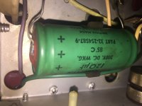
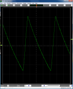
The unit now works without any mods. There is a large amount of hum due to the aging filter capacitors. I put a scope after the diode rectifier and the ripple is 20Vpp. Voltage at the first filter is 155V with 120VAC input which is close to what the schematic says.
1. Capacitors will be here today. I will change the filter capacitors (double to 240uF) first and then take measurements. If the ripple is small and the hum is gone I wont pursue a full bridge rectifier.
2. I will go ahead and change the rectifier diode.
3. Add a fuse to the mains side and on the B+ side as suggested. I was only going to do the mains fuse but B+ is a good idea too.
It looks like there are quite of few ceramic caps in the audio path. Would it be advised to change these? I know ceramics can be detrimental when used as coupling caps for audio. As pcan suggested, there could be unintended consequences when modifying components.
> quite of few ceramic caps in the audio path
It is a very pretty pig's-ear. If you want a silk-purse, get a silk-purse.
It will play music nicely. If you demand sole-sinking crystalline transparency with a rose bouquet and oak after-notes, go get such a thing. The "upgrade path" on this is essentially infinite.
I can hear a X7R cap but never minded it.
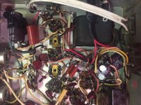
Recap Finished.
I have finished the recap. I completed the following.
1. I replaced the 120uF cap with two 120uF in parallel (240uf total) and a 1uF bypass film cap.
2. I replaced all the 80uF and 50uF with 82uF caps. I left the can capacitor alone and mounted a solder strip with a center ground tab. I was able to solder the ground tab of the solder strip over top of the bottom of the can capacitor. This way all my mods are reversible.
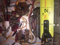
3. I replaced the 15k and 150 Ohm resistors with equivalent metal film resistors along the high voltage line.
4. I added a fuse on the B+ line and on the mains.
5. I had an inrush limiter handy so I added it too. Thought it would be a good idea since I increased the capacitance significantly in the power supply.
6. I changed the old power cord to a three prong and earth grounded the chassis.
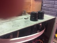
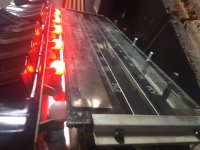
7. Replaced the burned out bulbs with new drop in LEDs (frosted orange).
8. I replaced the rectifier diode with a fast recovery 1A diode.
9. I added some banana jacks so that I could add external speakers if desired.
I captured the waveform after the rectifier and it measures close to 12Vpp. Before my mods it was around 20Vpp. See attached.
There is an audible 60Hz hum coming through. I am not sure where it is coming from inthe circuit yet. I am glad I didn't add the bridge rectifier since 120Hz would be much worse. It will be interesting to get it back into its cabinet and see what hum comes through.
The amp is definitely nothing special. It sounds really good at low volumes through my 8 ohm speakers (Mission 702e). However, it really distorts when I crank it up. I measured the power output just before the onset of distortion and I got 3.13 watts through 8 Ohms resistive load which is right on par.
The radio works really well. I can pull in stations like crazy on both FM and AM.
Overall the unit is good now. I am glad a didn't do anymore mods to it since it wouldn't be worth it. Hopefully the unit survives another 56 years!
Thanks for the help and feedback.
I have finished the recap. I completed the following.
1. I replaced the 120uF cap with two 120uF in parallel (240uf total) and a 1uF bypass film cap.
2. I replaced all the 80uF and 50uF with 82uF caps. I left the can capacitor alone and mounted a solder strip with a center ground tab. I was able to solder the ground tab of the solder strip over top of the bottom of the can capacitor. This way all my mods are reversible.
3. I replaced the 15k and 150 Ohm resistors with equivalent metal film resistors along the high voltage line.
4. I added a fuse on the B+ line and on the mains.
5. I had an inrush limiter handy so I added it too. Thought it would be a good idea since I increased the capacitance significantly in the power supply.
6. I changed the old power cord to a three prong and earth grounded the chassis.
7. Replaced the burned out bulbs with new drop in LEDs (frosted orange).
8. I replaced the rectifier diode with a fast recovery 1A diode.
9. I added some banana jacks so that I could add external speakers if desired.
I captured the waveform after the rectifier and it measures close to 12Vpp. Before my mods it was around 20Vpp. See attached.
There is an audible 60Hz hum coming through. I am not sure where it is coming from inthe circuit yet. I am glad I didn't add the bridge rectifier since 120Hz would be much worse. It will be interesting to get it back into its cabinet and see what hum comes through.
The amp is definitely nothing special. It sounds really good at low volumes through my 8 ohm speakers (Mission 702e). However, it really distorts when I crank it up. I measured the power output just before the onset of distortion and I got 3.13 watts through 8 Ohms resistive load which is right on par.
The radio works really well. I can pull in stations like crazy on both FM and AM.
Overall the unit is good now. I am glad a didn't do anymore mods to it since it wouldn't be worth it. Hopefully the unit survives another 56 years!
Thanks for the help and feedback.
Attachments


Last edited:


...I got 3.13 watts through 8 Ohms resistive load which is right on par.
One 25L6 at 110V gives 2.1W. At 132V we might expect 2.5W, or 5W the pair. Low-price output transformers should still be better than 80% efficient, 4 Watts.
Vintage consoles often used "3.2 Ohm" speakers, now called 4 Ohm. 8 Ohm load may be incorrect for extracting all the mighty power of this amp.
- Status
- This old topic is closed. If you want to reopen this topic, contact a moderator using the "Report Post" button.
- Home
- Amplifiers
- Tubes / Valves
- Clairtone S-401 Tube Amp Restoration