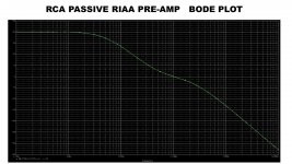
That original RCA circuit may need some tweaks in the time constants.....
I get simulated +/-0.2dB 40Hz to 300KHz, -1dB @ 23Hz.
Not bad for all Standard Values.
This sim is run with the Laplace function, which takes time-constants as Parameters.
Attachments
My first posting was off base... It was late and I goofed by making an assumption to simplify the math that later turned out to be an error on my part... I later derived the transfer function and seen where I goofed ... The RCA RIAA curve is truly very close to the RIAA curve.... I get similar +/- .2dB results as well... Truly good engineering considering they stuck to standard values... One trick that helped them achieve this with standard values is by attaching the .0033uF to the top of the .01uF cap.... instead of connecting the .0033uF straight to ground as is typically done.. I like how you implemented the Laplace function ...very cool...
Last edited:

My first posting was....
I like how you implemented the Laplace function ...very cool...
I think we nearly cross-posted, it was late here.
Not "my" implementation-- someone else here told me to use it. I think I simply squinted Koren's Laplace plan. As you see, I have been comparing it with Koren's passive iRIAA network, and I like the Laplace better.
The RCA "error" sims mostly as a dip at 1KHz. On a hunch I shimmed the "22k" to about 23.8K and get sub-0.1dB error.
The Laplace I use does not fool with any 20Hz or 50KHz kinks; I accept them as optional or even wrong. We see the RCA "does" implement a sub-sonic cut, though around 10Hz, and that is fine, even wise, if 50Hz is not compromised.
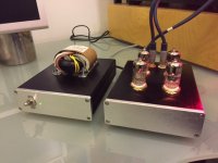
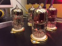
Hello to everybody, I finally finish my project and here the result.
The first attempt with just one 6922 tube failed as most of you already predict, so I decide
to do the project propose by WALTUBE, that I really thanks for the help he give to me, I just add 1k grid stopper resistor on the input and the coupling cap on the output to 3.3uF ClarityCap CSA, everything else is exactly as the project of WALTUBE especially the RIAA EQ.
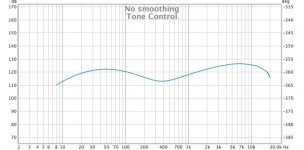
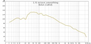
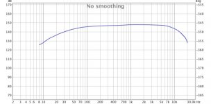
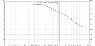
About the tubes this project was suppose to be for ECC82 and ECC83 but because I do not have those tubes but I have the 6922 and 6N2P-EV I give a try. I try first with all 6922 and the sound was ok, then with all 6N2P-EV sound was louder and clearer but with some unwanted noise, so I try to use on first input stage 6922 and on the second 6N2P-EV and bang…the difference was immediately noticeable, clear, open, good bass range and overall I like it so much, also very silent even at higher volume on my tube amp I cannot ear nothing from the speaker even if I put my ears there, so I am really impress for the result, I also check the frequency response with REW and look like to me very impressive.
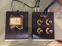
I also decide to build a separate power supply with separate B+ and heather also separate for the two channel, also the power supply schematic has been supply by WALTUBE, if somebody need it let me know, so here again thank you to everyone, I actually analyse from all of you all suggestion and precious information, so this successful project is actually a result of a brilliant team work. All the best to everyone.
Acky
The first attempt with just one 6922 tube failed as most of you already predict, so I decide
to do the project propose by WALTUBE, that I really thanks for the help he give to me, I just add 1k grid stopper resistor on the input and the coupling cap on the output to 3.3uF ClarityCap CSA, everything else is exactly as the project of WALTUBE especially the RIAA EQ.
About the tubes this project was suppose to be for ECC82 and ECC83 but because I do not have those tubes but I have the 6922 and 6N2P-EV I give a try. I try first with all 6922 and the sound was ok, then with all 6N2P-EV sound was louder and clearer but with some unwanted noise, so I try to use on first input stage 6922 and on the second 6N2P-EV and bang…the difference was immediately noticeable, clear, open, good bass range and overall I like it so much, also very silent even at higher volume on my tube amp I cannot ear nothing from the speaker even if I put my ears there, so I am really impress for the result, I also check the frequency response with REW and look like to me very impressive.
I also decide to build a separate power supply with separate B+ and heather also separate for the two channel, also the power supply schematic has been supply by WALTUBE, if somebody need it let me know, so here again thank you to everyone, I actually analyse from all of you all suggestion and precious information, so this successful project is actually a result of a brilliant team work. All the best to everyone.
Acky
Attachments
How much would the curve deviate if the input tube's rp deviates by 10%?
Very little, because of the cathode follower's low output impedance.
Last edited:
I've built this one with 6922 in the past, with good results: http://diyaudioprojects.com/mirror/members.aol.com/sbench101/Preamps/RIAA3.gif
From this site: Steve's Tube Pages
Build here: RIAA Phono Amp Design
From this site: Steve's Tube Pages
Build here: RIAA Phono Amp Design
Last edited:
kissabout2002,
That preamp looks good, and for sure sounds good.
As to my post # 29:
The input tube, a 12AX7 has a plate resistance, rp of about 62k to 80.5k Ohms. The plate load resistor is 100k Ohms. Or, if another tube is used, the same principles apply.
rp and 100 k in parallel drive the 0.1u and 470k series network, with that series network including the parallel resistance of 100k and rp (network #1). Network # 1 in turn drives the 22k and paralleled 0.0033u; which drives the 0.01uf to ground. The series network # 1 also drives the 680k to ground, and the 2nd stage 12AX7 miller capacitance.
12AX7 rp varies from tube to tube, and also with the standing current and voltage that the tube self biases at (also different from tube to tube).
My original question related to different rp values. If the rp is 71.25k Ohms, and varies +/- 10% (+/- 7.125k Ohms): How much does that effect the RIAA playback response?
How much would the curve deviate if the input tube's rp deviates by 10%?
There are *several* circuits in this thread.
The timing of your question *seemed* to follow posting of a plan where the EQ networks are isolated with cathode followers. If you are looking at a plate-driven plan, please say which one.
PRR,
The schematics in posts #2, #11, and #22.
My post #29 question followed the schematic in post #22.
Yes, these schematics appear to be the same, or at least similar; and do not have cathode followers as in some other posts in this thread.
The schematic in post #32 was after my original question in my post #29.
My post #34 referred back to my original question in post #29.
Last edited:
> My post #29 question followed the schematic in post #22.
#22 was two months ago. Yesterday Acky posted a different plan, and the same day you asked "How much.." without any reference, confusing Acky, Rayma, and me.
62k to 80.5k = +/-14%
assume 2% resistor, 98k to 102k
62k || 98k = 38k
80.5k || 102k = 45k
difference is 7k, but assume 8k change
By inspection of the circuit, the main change is to the 50Hz pole.
1KHz gain changes 0.13dB.
We always have a Volume knob and ideally will normalize for the 700Hz center or 300Hz-3Khz body of the music.
Normalized error at 50Hz is 0.040dB; at 20Hz, 0.067dB.
Attachments
Last edited:
I am using, as possible, a low Rp tubes and low value of resistors.
At the end the s/n will be interesting with a good numbers, with a regulated power supply.
The use of gain stage + CF can allow you also to change the gain ( 4 to 6 dB) only inserting the bypass cap on cathode of the gani stage without any changes on riaa curves.
The lasts stage I made was with a pentode in triode connection; the gain goes from 42 to 48 dB and the s/n is around 78 dB weighted.
I will publish an article on Audioreview in Italy in next time.
Walter
- Status
- This old topic is closed. If you want to reopen this topic, contact a moderator using the "Report Post" button.
- Home
- Amplifiers
- Tubes / Valves
- RIAA network on cathode follower