The “corrections” you mentions should be applied to the BOM, and the mods to the PSU PCB done, assuming you are using the first version of the PCB. Marc made the change to the PCB design recently, but those are not available yet.
The bias current will depend on the B+ one feeds it and class of operation (i.e. Class A, AB or somewhere in-between), and of coarse observing the maximum dissipation of the tube.
I believe you have not mentioned what B+ you are aiming for. I should have pointed out that the suggestions above for the choke assumes a middle-of-the-road bias current and B+ of 400Vdc. As a rule of thumb with fixed bias and 400Vdc between anode and cathode, an EL34 should be biased between 30 and 44 ma for class AB. Aiken wrote: “... an EL34, in class AB operation at 400V, with a 4K plate-to-plate primary impedance, would be biased at 40mA, while the same EL34 tube, used in a true class A circuit at 250V, might be biased at around 100mA”.
See: The Last Word On Biasing
Hope this helps. Some input/discussion from builders on their favorite operating point of the EL34 in BH would be very helpful.
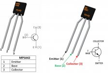
MPSA42 will work fine
BUT
The "goodness" of a current source is its AC impedance..
That is dependent (mostly) upon the Hfe (beta) of the bottom transistor which has very low voltage across it. So use MPSA42 for the top transistor but use something like a BC547C for the bottom transistor.
NOTE the A, B, C denoted the gain of the transistor and so you want a "C:" for optimum results.
Cheers
Ian
Hi everyone,
Based on this document: http://www.oestex.com/tubes/Rudolf Moers - Appendices.pdf
EL34s in pentode mode can bring the anodes down to 30V being still in AB1, but with 43%v UL taps they can go down to around 150V only (see page 17).
It seems impossible to find Wg1 for EL34, mainly because in pentode mode there's no need to go into AB2, so I would like to ask to someone who built and tested this amp, how the EL34s react to powerdrive, and how deep it can be done.
Based on those curves, g1 at +10V will bring the anode back to +50V circa, but will g1 resists to that stress?
Thanks in advance for anyone's help.
First note, I apologise if asked elsewhere in threads relating to the BH projects.
Has anyone looked at running 807's in a Baby Huey? My parts have started to arrive with the Toroidy transformers being the last order I need to decide on. Had planned on a stock EL34 build but now thinking 6L6 / 807. need to lock in my OPT's")
Any thoughts or experience welcome
Has anyone looked at running 807's in a Baby Huey? My parts have started to arrive with the Toroidy transformers being the last order I need to decide on. Had planned on a stock EL34 build but now thinking 6L6 / 807. need to lock in my OPT's
Any thoughts or experience welcome
I'm actually considering a Loctal socketed version, so I can use 7C5 (á la 6V6) or 5B/255M (which is an 807 on a Loctal base). I have looked at how the sockets could be fitted, and if the base is rotated one pin, then there are a just a couple of traces affected, and nothing that cannot be circumvented.
The 807 would not tolerate the high screen voltages of the EL34 BH version, so it would have to be running as a triode with max 400V on the plate, if I was not to add a regulated screen supply. I haven't looked closely enough yet to see if this negates the benefits of the BH design.
I am still building and musing on how I shall use it. Interested on your thoughts on thsis!
Being an 807 fan, I'm always on the lookout for old amp schematics. I've seen several where they run them as triodes at 415v. I recently saw one where they were connected as ultra-linear at 440v. I suppose one could try that - if you had a good supply of replacement 807s (1625s) on hand.
Hi @ OldHector
The 5B/255M is an interesting variant, A reseller here in NZ had a pile of them he was trying to sell, assume they would be long gone now. If you went down that route I'd probably just wire the socket to the PCB and save cutting traces
The more I think about it the more I think I should stay with the stock EL34, Ive never used them before!
Has anyone built the EL34 BH with EL509?
Seems a perfect tube for the purpose, as it has a a transconductance of 18000 uS and a plate resistance of 8 kOhm plus 35W of plate dissipation ( http://ekladata.com/Pw1_EIWx_5D-1f2huY5k40HrDX8/el519.pdf ). So plenty of power, an already low plate resistance and alot of transconductance to be able to apply alot of shunt feedback without needing too much swing from the PI. It just needs a dedicated tertiary winding to apply UL.
Seems a perfect tube for the purpose, as it has a a transconductance of 18000 uS and a plate resistance of 8 kOhm plus 35W of plate dissipation ( http://ekladata.com/Pw1_EIWx_5D-1f2huY5k40HrDX8/el519.pdf ). So plenty of power, an already low plate resistance and alot of transconductance to be able to apply alot of shunt feedback without needing too much swing from the PI. It just needs a dedicated tertiary winding to apply UL.
Interesting suggestion! I have a dozen EL509s in storage. Hmmm! The question is where to obtain good but affordable output transformers with a special separate screen windings for EL509? Do you know?
Or perhaps such an output transformeris not really necessary, unless you need big power. Kjeld Pederson’s “Final” Amp design attached, uses 300Vdc in a conventional UL transformer with 1900 Ohm primary to deliver a reported 80+ watts.
Due to my speaker efficiency I don’t need a lot of power, so I probably wouldn’t try an EL509 BH, but it is tempting. I actually have decided to build a BH using Russian 6P15P (S=15 vs 11 mA/V for EL84) as well as an amp with 7591-type output tubes (I have 6GM5 actually), with the same reasoning to utilize the high GM.
Attachments
If you want to extract the maximum power out of a pair of PP EL509, using a tertiary winding for the screens, a core capable of well over 100 watts is likely to be needed. While I happily own several Toroidy power and output transformers, their largest core is good for “only” up to 80 watts, so they would not be able to wind one for max power on a EL509.
Last edited:
Thanks for the schematic, I will try some simulations with the 6KG6 model I have, and see if there's a way to use the BH EL34 boards, but I see hard times for the 12AX7. New ones (I've seen one with a gain stage after the PI and autobias) will absolutely perform better.Kjeld Pederson’s “Final” Amp design attached, uses 300Vdc in a conventional UL transformer with 1900 Ohm primary to deliver a reported 80+ watts.
I'm using 6P14P-EV in my project, and 6N2P-EV for the phase inverter. I've heard good things about them, both for sound and reliability.I actually have decided to build a BH using Russian 6P15P (S=15 vs 11 mA/V for EL84) as well as an amp with 7591-type output tubes (I have 6GM5 actually), with the same reasoning to utilize the high GM.
I'm now playing music on my Klipsch with a pair of EL34 per channel (and sometimes a class D amp), I don't need 80W either, but it would certainly be a good tube for the purpose. I guess I need to read some threads about drivers for SE triodes to find a good phase inverter tube for the EL509 in this configuration.While I happily own several Toroidy power and output transformers, their largest core is good for “only” up to 80 watts, so they would not be able to wind one for max power on a EL509.
Thanks for the schematic, I will try some simulations [of Kjeld Pederson’s “Final” Amp] with the 6KG6 model I have, and see if there's a way to use the BH EL34 boards, but I see hard times for the 12AX7. New ones (I've seen one with a gain stage after the PI and autobias) will absolutely perform better.
.
Roberto,
The “Final” Amp design is one I’m eager to build after the Baby Hueys. I have a pair of Plitron output transformers perfect for this amp already, but was unsure what driver/inverter tubes to use, since Mr. Pederson gave several options without associated part values. I’m not skilled (yet) with circuit simulation myself, so I would be VERY interested in your simulations of the ”Final” circuit. (Apologies for the OT diversion to all Baby Huey fans).
Kind wishes,
Francois
- Home
- Amplifiers
- Tubes / Valves
- EL34 Baby Huey Amplifier