Answering a question above.
The + supply for the MOSFET Drain is determined by 2 things:
Too high and you just end up dissipating extra power in the MOSFET.
Too low and the Crss (Capacitance from Drain to Gate) varies with Drain to Source Voltage which can mess up high frequencies in particular.
The MOSFET Datasheet is here:
https://www.st.com/resource/en/datasheet/stu9hn65m2.pdf
Look at the graph labelled Figure 11.
The Source will have the audio signal on it. You want enough +ve Drain voltage such that on signal +ve peaks you still have around 30V (ideally 50V) across the MOSFET Drain to Source. For that voltage, the Capacitance is low and steady (not changing ). The +ve Peak of the audio signal on the Source will be around 0V so Minimum of say +30 to +50V for the Drain Supply.
Cheers,
Ian
The +ve Peak of the audio signal on the Source will be around 0V so Minimum of say +30 to +50V for the Drain Supply.
Cheers,
Ian
Thank you for your clear explanation and the Mosfet datasheet. The recommended TOROIDY TSTA 0250/001 power transformer, and the Mk 2 PCBs are arranged to provide +15 Vdc from a 6.3 Vac doubler supply for the Mosfet Drain Supply.
If I understood you correctly we would we be better off aiming for +30 to +50 Vdc Drain Supply. Figure 11 in the Mosfet datasheet shows that Crss begins to level out above about 70 Vds, so would +50 Vdc or higher even be preferable?
Yes - we would be better off with +50V or +70V DC for the Drain but we are in the realm of diminishing returns.
We could also have chosen something like:
https://www.st.com/content/ccc/reso...df/jcr:content/translations/en.CD00003138.pdf
If you check the equivalent Capacitance vs Vds graph you see it level out at 20V BUT Crss is more than 10 times higher to start with.
The device (STU9N65M2) that Marc chose has unusually low Crss and is a great choice.
Cheers,
Ian
Last edited:
R33 and R38 in the CCS loads set the current in the Source Followers. I = Vbe of 2N5551/390 Ohms = 0.65/390 = 1.7mA
Assume -100V for B- If you went to say +70V for Drain (in lieu if the =15V there now) then worst case Vds could be 170V and worstcase (peak) dissipation in MOSFET would be 170 x 0.0017 = 0.28 Watts
More typically, the Source will sit at the output tube bias volts, say -50V for KT88, with Vdrain = +70V gives 120V Vds average (audio signal will cause Vds to swing either side of that) and dissipation would be 0.2 Watts. So MOSFET dissipation would not be a problem.
Dissipation in Q7 and Q8 in the CCSes is likely to be more critical. Currently about 120mW of the 625mW allowed.
Even so in the vein of "Diminishing Returns" I would be tempted to change R33 and R38 to 270 Ohms for 2.4mA in the CCS. This change to make sure that the Miller Capacitance at the output tube grids can be charged and discharged fast enough to keep up with the audio signal and we don't suffer slewrate limiting.
Lets check that - More fluff / Ian's possibly dodgy algebra plus some best guess ("butt pluck") requirement values.
If we want to swing say 100V peak to peak at 100kHz (to suit KT88 biased at -50V) then some maths or an online slewrate calculator will tell you we need 62.8 V/us. (slewrate = 2 pi F V)
Assume a Miller Capacitance at the output tube grid of say 50pF
Fundametal (1st principals) Capacitance Formulae: C = q/V - where q = charge
so C = i.dt/V (i.dt = current x time substituted for charge)
we know that dV/dt = slewrate = 62.8 V/us so 50 pF = i x (1/slewrate)
and rearranging we get i = 0.0031 or 3.1 mA.
Since the source followers are running at 1.7mA that means we will not achieve that slewrate calculated above.
Pushing the CCS currents to greater than 3.1mA (to achieve that calculated slewrate) will start to stress the 2N5551 dissipation but could be done if a small heatsink is added to Q7 and Q9.
In view of these possibly dodgy calcs I would be using 270 Ohms for R33 and R38 for CCS current of 2.4mA. That will get you to 100V pk-pk at up to about 70kHz.
If you are "game" R33 and R38 = 180 Ohms will get you to 100kHz (3.6 mA in the CCSes) but Q7 and Q9 would be dissipating nearly half of their 625mW rating and would want small clip on heatsinks. Do you need 100kHz drive? probably NOT.
Cheers,
Ian
Last edited:
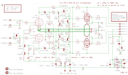
Help! EL34 Baby Huey LtSpice simulation
hello folk,
can someone help me with a ltspice simulation for schematic below
I saw this amplifier is very made by a lot of people, i want to build this but befor to start i want to see a simulation with this, how is frequncy response? what is the output power? what distorsion have for max output power?
thank you
Attachments
I’m “game” all the way. Really helpful for the “less-electronically gifted” . Thanks so much.
This opens the doors beyond the confines of the “intended power tubes”. I had already planned to use the GB boards for NOS Russian 6P41S and perhaps 6P36S tubes, but your explanation helps to make it much more of an rational/engineering effort. I have always wondered how to determine the drive capabilities of the Baby Huey topology.
This opens the doors beyond the confines of the “intended power tubes”. I had already planned to use the GB boards for NOS Russian 6P41S and perhaps 6P36S tubes, but your explanation helps to make it much more of an rational/engineering effort. I have always wondered how to determine the drive capabilities of the Baby Huey topology.
Last edited:
Hello Prasi,
Thanks for the PCB, they are just arrived and are very nice as usual")
I am not in favor of a new thread, it will only make things more confusing. I have already started this thread because of the change from EL84 in the original Ian thread to the EL34 version... There is also someone who started a Wiki thread and there is the GB thread ! Too much thread make the information difficult to find and some time errors between different posts
Therefor I will stay on this thread only, but I have no problem to publish information again about schematic and BOM for the EL34 Baby Huey MK2
There is no stuffing guide yet since I have not yet build the MK2 version but the principe is very close to the first version with the advantage to have the serigraph on both sides of the PCB
You can also read the comments from Ian for KT88 version with voltage options up to 50V for the driver stage but with -100V for bias be careful with 2N5551 which are specified at 150V voltage !
Personally I am not a big fan of KT88, the ones I have tested on my Jolida amplifier sounded too hard, I prefer the 6550 that I am using now, I may try them on the MK2 ?
Cheers,
Marc
Thanks for the PCB, they are just arrived and are very nice as usual
I am not in favor of a new thread, it will only make things more confusing. I have already started this thread because of the change from EL84 in the original Ian thread to the EL34 version... There is also someone who started a Wiki thread and there is the GB thread ! Too much thread make the information difficult to find and some time errors between different posts
Therefor I will stay on this thread only, but I have no problem to publish information again about schematic and BOM for the EL34 Baby Huey MK2
There is no stuffing guide yet since I have not yet build the MK2 version but the principe is very close to the first version with the advantage to have the serigraph on both sides of the PCB
You can also read the comments from Ian for KT88 version with voltage options up to 50V for the driver stage but with -100V for bias be careful with 2N5551 which are specified at 150V voltage !
Personally I am not a big fan of KT88, the ones I have tested on my Jolida amplifier sounded too hard, I prefer the 6550 that I am using now, I may try them on the MK2 ?
Cheers,
Marc
Attachments

Mouser BOM Baby Huey MkII
Hi Marc and all other Guys,
today I have ordered the first parts for the Baby Huey MkII and stumbled over one problem.
In the original BOM from Marc (Revised September 2019) there is CX1 with a value of 10nF and 1000V but the order Number RDER72J104K4M1H03A belongs to a capacitor with 0,1uF (100nF) 630V.
I think the Voltage is not a problem, but which value is the right one?
Not so an important information, the resistors R33 and R38 seems to be not available at Mouser, they have an alternativ one from Yageo.
The link to the BOM (with all parts you can order for this project at Mouser) is at the end.
Attention: The BOM is for one PCB, for a normal stereo set you must order it twice!
It includes both Versions of CX1, the original order number in the original sequence, the original value at the end named as: CX1 alternativ; R33, R38 is replaced with the Yageo parts!
Have lot of fun during the build and listening!
Kind regards
André
Link: https://www.mouser.com/ProjectManager/ProjectDetail.aspx?AccessID=d65300aacc
Please copy it before editing or changing.
Hello André,
Thank you for your feedback
All your remarks are very exacts and useful. For CX1 the value is not critical, it is just a HF decoupling and since I had plenty of 10 nF 1000 V in stock I use them, but a 100 nF 630 V can be used too, be careful with the size however !
Best regards,
Marc
Thank you for your feedback
All your remarks are very exacts and useful. For CX1 the value is not critical, it is just a HF decoupling and since I had plenty of 10 nF 1000 V in stock I use them, but a 100 nF 630 V can be used too, be careful with the size however !
Best regards,
Marc
Are Gerber files (or maybe even Eagle files, so one can customize) available for the EL34 Baby Huey? I see people mention getting boards, but don't see how they were obtained. Group buys, and their restricted timing, don't seem to make sense any more when one can get PCBs cheaply from sources like JLCPCB. For example, I got five 6"x6" boards for $35 (including shipping) for my turntable project:
Philips 212 (GA212) Turntable Upgrade | lensprojects
I understand if files are not freely available because someone wants to make a bit of cash for their efforts, but if that is not the limitation, maybe they can be posted somewhere?
Philips 212 (GA212) Turntable Upgrade | lensprojects
I understand if files are not freely available because someone wants to make a bit of cash for their efforts, but if that is not the limitation, maybe they can be posted somewhere?
Are Gerber files (or maybe even Eagle files, so one can customize) available for the EL34 Baby Huey?
......for my turntable project:
Philips 212 (GA212) Turntable Upgrade | lensprojects
Welcome Mr. Lens! Your points about inexpensive custom PCBs are well taken; applicable to skilled folks. The Group buys that Prasi ran for the Baby Huey builders were really well done and inexpensive, delivering superbly made boards to some of us who lack the requisite skills. Unfortunately I think all the boards are spoken for at this point.
I looked at your web wordpress site and thoroughly enjoyed your turntable project and meticulous documentation of it, as well as your other impressive efforts. Thanks for sharing your experience. If you choose to build one you will be an asset and resource to the other Baby Huey builders.
If you are willing to document your EL34 Baby Huey project I have an extra pair of Mk 1 boards I will mail to you for free. Just PM me.
Quick question, is there a mouser project for the power supply BOM?
I used the one from André (thanks!) for the MK II boards, but I haven't seen a link to one for the power supply.
If nobody has one I'll try to figure out how to do that when I order the parts and build one.
Thanks, gabo
FYI, Heretik HiFi - you can go to Mouser and export the BOM to an excel sheet.
I used the one from André (thanks!) for the MK II boards, but I haven't seen a link to one for the power supply.
If nobody has one I'll try to figure out how to do that when I order the parts and build one.
Thanks, gabo
Is there an excel version of the BOM having some issues with the .PDF
Thanks.
FYI, Heretik HiFi - you can go to Mouser and export the BOM to an excel sheet.
Last edited:
Also there are some discrepancies between the power supply BOM and the printed information on the board.
Component................BOM PDF............................Printed on board
C7.............................220uf, 25v.........................2200uf, 25v
C4.............................0.15uf, 160v.......................2uf, 160v
C5.............................0.15uf, 160v......................1uf, 160v
C6.............................0.15uf, 160v......................100nf, 160v
C9.............................10uf, 25v...........................33uf
I haven't checked the circuit, but I suspect these make little to no difference. Just makes it easier to populate the board if the values of what you're putting in match what's printed on the board.
thanks, gabo
Last edited:
- Home
- Amplifiers
- Tubes / Valves
- EL34 Baby Huey Amplifier