Hello Francois G, I want to say straight up front, “I do not have a horse in this race”. That being said, I don’t understand where your snarky bitterness is stemming from? Marc has been extremely supportive through the BH process. He has always answered questions in a timely matter for myself and other members with BH build questions. He even spent the time and effort to release a build guide written in ENGLISH!! But, this is a DIY forum which does mean that members/builders are expected to do there own due diligence with respect to the project they are involved with. I don’t recall Marc making an “implied promise” to you or anyone about his plans. Your hurling insults towards Marc, and now Bfpca, are simply uncalled for. If you really think Marc’s boards are “inadequate, lacking and without innovation” just move on to another project. Regards, VunceI stand by the inadequacy of the original PCB, as Marc apparently is too, since he is trying to separate the main board and PSU. My request was MERELY for more information about the new PSA board, which caused Marc’s untimely blowup. Marc’s response rate to the thread is my main concern - he has been mute for several weeks if not months. If thread starters are not willing to respond to requests for information in say a reasonable 14 days, they should not start threads. Neither should diyAudio accommodate that. Perhaps Marc is too busy with his new interest, the Simple Mosfet amp, which is fine if there is no implied promise to help people who bought into his BH boards, like me.
Vunce, there is no "like" button on the forum (or if there is I can't find it). So I'll just have to respond with a "like" and a thumbs up for your comment.
This is a really great project, an easy build, and the guys running it have been nothing but first class in all aspects. The group buy I was a part of was run flawlessly and I have no issues with the design.
Even the original boards allow for an easy build that works great. Or if you don't want to use the onboard rectifier, you can choose to upgrade a bit and do your own power supply.
So, just for myself, I want to give a big thanks to marc, bfpca, prasi, vunce, and a few other people I've probably missed for all the help!
Not only for the design, boards, and group buys, but also for recommendations on transformers, external power supplies, meters, and chassis builds.
There is certainly enough good info in this thread to build a complete and very well performing amp that will give many years of service.
gabo
Francois, I have had enough of your snarky comments. Remember this proverb "It is better to be thought a fool than to open ones mouth and remove all doubt". I came late to the Baby Huey EL34 GB. Instead of being expedient, I read every posts about the project in order to learn everything about what others have contributed to it. I am still working on the BH EL34 slowly but surely. Reading from your posts, I already know that you have not read all the posts. This is DIYaudio, not DIFMaudio (Do it for me audio). Gingertube, Bandol et. al. contributed the circuit design and board design out of goodness of their heart. If you don't like the board design, just do your point to point connections. You can have any BF capacitors you want and be done with it.
Better yet, design your own "improved" power supply board and contribute to the community instead of complaining as if someone owes you something. No one owes you anything and no one promises you anything on this board. This is DIY. The most ridiculous thing was that you kept saying you bought 4 sets of boards as if you were a savior of the project. If you did not buy them, it just meant 4 less sets of board purchased from the board manufacturer. Prasi wouldn't shed a tear. Besides, why did you buy 4 sets of board without studying the board design. This again shows that you did not do your due diligence.
Better yet, design your own "improved" power supply board and contribute to the community instead of complaining as if someone owes you something. No one owes you anything and no one promises you anything on this board. This is DIY. The most ridiculous thing was that you kept saying you bought 4 sets of boards as if you were a savior of the project. If you did not buy them, it just meant 4 less sets of board purchased from the board manufacturer. Prasi wouldn't shed a tear. Besides, why did you buy 4 sets of board without studying the board design. This again shows that you did not do your due diligence.
Francois, I have had enough of your snarky comments. Remember this proverb "It is better to be thought a fool than to open ones mouth and remove all doubt".
Well, mr. bbqrooster. You seem to have extensive knowledge about me and you are not shy to spread it. I do not mind it, but I want to be clear that I insulted no one, and only wanted more expedient information about Marc’s new power supply board.
Your hurling insults towards Marc, and now Bfpca, are simply uncalled for.
Not sure where you get this perspective. I have not and will not say anything negative about Bfpca. I really enjoyed his experimentation and his reporting of it.
I bought 4 pairs of the BH boards and after I received them I looked and realized that the design is really not very smart. You tried to optimize for size, but DIY people want to optimize for best sound and ease of construction, with generous capacitor sizes, and a few € extra does matter not much. That is why I am interested in the new boards.
This statement was definitely clumsy and I am sorry about that. Apologies to Marc. I liked the PCB design as a very efficient use of quare cms.
I’m not sure why everyone is so negative towards me. I merely wanted Marc to provide more information about his new powersupply PCB.
I’d like to see a build post on the EL84 and el34 that starts and finish with just the builds and not all the great mods people are doing It’s very hard to understand what’s going on when people go off in all kinds of different things they are doing and not really talking about the step by step build of the boards More so on the EL84 I’d just like to see a post started with just doing the build with the parts being used And then after that’s done start a post of how they added all the other goods to them I’d really like to see this with the EL84, I know That there are many post on these, but show me one that’s a true from start to finish of just building the pcs boards and not all the added stuff. We have to build it first before we start doing the mods!! Right ? I’m a newbie here and I’ve asked my questions about the build and get treated like I should know all the answers These were advertised as a newbie type build.
Well I’m sitting here with a pile of parts that I don’t even want anymore I’ve been reading a ton of these builds and they all sound great. If I only knew what the H people were saying with the high level of tech talk. Don’t get me wrong here, all the guys that did the ground work for these, my hat off to you guys and a big thanks for all your time and effort And yes I have been pointed to this post, that post and every other post about these and they all go off into lala land with the builds. Like this post has gone into the wrong direction, with my help as well on driving it that way , sorry. But had to say my peace. So if someone wants to buy my EL84 boards and all the parts. Please message me and let’s make a deal. I’m in the USA and will ship it all to you. And no I’m. Not going to give it away. Thanks for letting me vent me two cents onto this post
Well I’m sitting here with a pile of parts that I don’t even want anymore I’ve been reading a ton of these builds and they all sound great. If I only knew what the H people were saying with the high level of tech talk. Don’t get me wrong here, all the guys that did the ground work for these, my hat off to you guys and a big thanks for all your time and effort And yes I have been pointed to this post, that post and every other post about these and they all go off into lala land with the builds. Like this post has gone into the wrong direction, with my help as well on driving it that way , sorry. But had to say my peace. So if someone wants to buy my EL84 boards and all the parts. Please message me and let’s make a deal. I’m in the USA and will ship it all to you. And no I’m. Not going to give it away. Thanks for letting me vent me two cents onto this post
Hello Vunce, gbowling, bbqrooster,
Thanks for your support, I appreciate a lot because it take me time to do all that work and it is difficult for me to explain things in English because it is not my mother language and some time I don't understand some expressions and negative criticisms give me the impression that I should not spend more time to communicate hopefully you are there to motivate me to continue
 ")
I am not a designer of amplifier, I have been working in embedded computing,but since I have bought a Jolida tube amplifier about 20 years ago, I have been interested to build tube amplifier BUT I wanted to take advantage of modern semiconductors to have the best of both world
That's why I was very interested by Ian thread for the Baby Huey
After his last suggestion, I made the change for the trimmers and today I did not go to the parade for the French National Day but I finished some cosmetic changes on the MK2 version 1.5 and I think it is now ready for the PCB manufacturing...
I repeat that this version has not been tested but it use exactly the same schematic that the first version and should work without problem. Now if some members of this forum want to take the risk and if Prasi can produce the PCB, it is time to check if there is enough interest to produce it ?
Because of the rules of the forum, I suggest to use this address to register your interest with the indication of MK2 PCB : GB for Baby Huey PCB If there is enough demand and if Prasi accept to do it, we may have an other round of EL34 Baby Huey production...
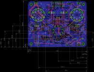
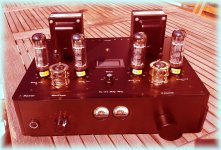
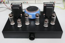
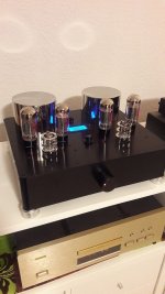
You can find below the last schematic and PCB of version 1.5 as well as the pictures of my EL84 and EL34 Baby Huey as well as the one of Philippe with nice Toroidy transformers...
Cheers,
Marc
Thanks for your support, I appreciate a lot because it take me time to do all that work and it is difficult for me to explain things in English because it is not my mother language and some time I don't understand some expressions and negative criticisms give me the impression that I should not spend more time to communicate
hopefully you are there to motivate me to continue I am not a designer of amplifier, I have been working in embedded computing,but since I have bought a Jolida tube amplifier about 20 years ago, I have been interested to build tube amplifier BUT I wanted to take advantage of modern semiconductors to have the best of both world
That's why I was very interested by Ian thread for the Baby Huey
After his last suggestion, I made the change for the trimmers and today I did not go to the parade for the French National Day
but I finished some cosmetic changes on the MK2 version 1.5 and I think it is now ready for the PCB manufacturing...I repeat that this version has not been tested but it use exactly the same schematic that the first version and should work without problem. Now if some members of this forum want to take the risk and if Prasi can produce the PCB, it is time to check if there is enough interest to produce it ?
Because of the rules of the forum, I suggest to use this address to register your interest with the indication of MK2 PCB : GB for Baby Huey PCB If there is enough demand and if Prasi accept to do it, we may have an other round of EL34 Baby Huey production...
You can find below the last schematic and PCB of version 1.5 as well as the pictures of my EL84 and EL34 Baby Huey as well as the one of Philippe with nice Toroidy transformers...
Cheers,
Marc
Attachments
Marc and others, For info - with EL34 output tubes R14 and R15 may not be large enough. Some years ago I built the Menno VDV70/100 with Plitron PAT4006. It specified 150 Ohm screen resistors but it suffered "Squegging" oscillation in Ultralinear mode. I had to increase the screen resistors to 1K to cure that. I would suggest using 1K for R14 and R15 at build time, just to avoid possible problems.
Looking forward to seeing the quad output tube, ultralinear + cathode feedback design whenever you get to it. I have a pair of VDV-2100-CFB/H output transformers on my shelf . http://www.amplimo.nl/images/downloads/ds vdv/vdv2100cfbh.pdf
Note that the 33% Ultralinear Taps plus the 10% Cathode Feedback taps mean that you actually get 10% Cathode Feedback AND 33 +10 = 43% Ultralinear Feedback.
Cheers,
Ian
Marc and others, For info - with EL34 output tubes R14 and R15 may not be large enough.
Hi Ian,
Is this only with EL34 tubes or has to do with other tubes, like 6CA7? If resistors need to change to other values, please let me know.
Many thanks,
bekim
Hello all,
Please post your requirement of PCB in the GB thread here.
GB for Baby Huey PCB
Already updated the list with mravinsky and cbueche requirements.
regards
Prasi
Please post your requirement of PCB in the GB thread here.
GB for Baby Huey PCB
Already updated the list with mravinsky and cbueche requirements.
regards
Prasi
I have ONLY seen the problem with EL34. If you look at the original Mullard application notes for EL34, you will see that they stated you should use 1K (per valve) screen resistors for ultralinear mode. If building an amp for 6CA7 then it makes sense to do so that you can plug in EL34 as well - so I would use 1K there too (also KT77).Hi Ian, Is this only with EL34 tubes or has to do with other tubes, like 6CA7? If resistors need to change to other values, please let me know. Many thanks, bekim
For other tubes 6V6, 6L6GC, KT88, KT66 etc. I would look at datsheets or application notes if you can find them. The 270 ohms is what I used for 6V6. I would suggest 1K as the "Universal" value BUT if using some of those othetr output tubes, than you may want to fine tune to a smaller value once up and running.
Cheers,
Ian
Last edited:
Hi rongon,
The idea of an MK2 version came after I have seen that several builders, including me, added some external power supply filtering to improve hum reduction and I took opportunity of this redesign to make other small changes, this is the list you are looking for :
1) Removed all rectifier diodes to use the MK2 power supply, but still use the on board capacitors for better on board additional filtering.
2) Modified Vdriver and Vbias value for more bias voltage margin with KT88 output tubes and R32 & R37 connected directly to Vdriver (based on Bfpca suggestion post 442)
3) Added heater jumper to accept ECC81 or 6N2P pinout
4) Increased voltage of capacitor C1 & C2 at 630 VDC (based on Ian remark post 452)
5) Connected both Vbias trimmer R41 & R42 in the same direction (as per Ian suggestion in post 498)
6) Used different connectors for better and easier wiring
7) And last but not the least, I made the serigraph visible from the bottom for easier assembly Pinout of the tubes has been reversed !
All these modifications were done while keeping the same mechanical dimension to make it possible to upgrade existing enclosures...
Until the Group Buy has enough request, please take time to have a look at the final version 1.5 to send me a comment if there is something that you may find strange or wrong
Best regards,
Marc
The idea of an MK2 version came after I have seen that several builders, including me, added some external power supply filtering to improve hum reduction and I took opportunity of this redesign to make other small changes, this is the list you are looking for :
1) Removed all rectifier diodes to use the MK2 power supply, but still use the on board capacitors for better on board additional filtering.
2) Modified Vdriver and Vbias value for more bias voltage margin with KT88 output tubes and R32 & R37 connected directly to Vdriver (based on Bfpca suggestion post 442)
3) Added heater jumper to accept ECC81 or 6N2P pinout
4) Increased voltage of capacitor C1 & C2 at 630 VDC (based on Ian remark post 452)
5) Connected both Vbias trimmer R41 & R42 in the same direction (as per Ian suggestion in post 498)
6) Used different connectors for better and easier wiring
7) And last but not the least, I made the serigraph visible from the bottom for easier assembly
Pinout of the tubes has been reversed !All these modifications were done while keeping the same mechanical dimension to make it possible to upgrade existing enclosures...
Until the Group Buy has enough request, please take time to have a look at the final version 1.5 to send me a comment if there is something that you may find strange or wrong
Best regards,
Marc
Bit of a KT88 fan myself.
The BH scheme basically trades off output tube gm for reduced rp (output tube internal impedance) which reflects to the secondary of the output tranny as reduced source impedance (better speaker damping). So it works best with high gm output tubes. That is tubes like EL84, EL34, KT88 (6550), KT77.
So why the hell am I running a BH with 6V6 in my lounge room HiFi system?
Coz it's gorgeous, not optimum, far from it, but just lovely.
I guess I like more even order distortion. But then being a professional design Eng in the day job I' have applied that to the home sound system and tried many options.
My least favourite amp of all time (cold , sterile and boring) was a top of the line Rotel 215W per channel Solid State 0.0001% distortion. After listening to it I decided there was something wrong with it and paid A$50 for a factory service manual and did a full setup of it -only to conclude that it was working perfectly to its design and just didn't suit my musical taste. It didn't matter what music I played, there was just no emotional engagement.
So I like distortion (of the right type) and the BH design is unappologetically NOT a low distortion design. Any opinion that it is a great low distortion HiFi design is actually quite wrong. It is its distortion characteristic which makes it "great". Well OK at least. Doing Full disclosure - "Suits Gingertubes tastes" - and from the fact that there have been 300 or so
builds by other folk , it suits their tastes too.
The balanced shunt feedback throws the maximum demand back upon the triode differential phase splitter amp and it (the phase splitter) contributes a fair bit to the final "sound" of a BH Amp. That is the same as saying that the choice of output tubes is less important, which is not entirely true. I like 6V6 but I would be the first to say that the 6V6 BH is not "technically" as good as the same amp with EL84. I just like its "warts". Of course I also use 6SL7 for the diff amp so that is contributing to "MY" sound.
You will have noted from the EL34 BH Thread that I have some VDV-2100-CFB/H "Super Dooper" Output Trannies on the shelf along with the companion Plitron Torroidal Power Trannies. They will dictate my next BH design and a quad of KT88 is what I intend for those trannies. Tossing up between full bore no adjustment needed ever with full bias servo solid state circuitry and the KISS - Keep It Stupid Simple design. (most folk get that KISS acronym wrong).
Of course if folk here want me to prototype new amps with quad of output tubes then that would be facilitated by sending me a couple of FREE Issue 1 PCB's.
I've actually been a bit miffed (probably without cause - coz I put the design into the public domain, that no one has offered me an "experimenters" pair of boards before now. Very special thanks to the DIYAudio member who expressed his thanks by sending me a quad of NIB Siemens EL81 to try out in the BH scheme. You know who you are. I am also fairly sure that your EL81 implementation is quite stunning.
I owe you an apology in return, maybe. I afraid I put your tubes into my Guitar Amp. I pulled the 6M5 I was using which were lovey to use your EL81 which were just superlative.
Cheers,
Ian
Last edited:
An addition to the above. What happens when you use parallel output tubes ? We use the concept of an effective single tube in lieu of the pair where: The effective gm is doubled (x2) The effective rp is halved (divide by 2) The mu (Va/Vg1) stays the same For maximum power Raa of the Output Tranny is halved. This can lead to really interesting options which would not be immediately apparent. Example: Hammond 1650 T with Raa of 2K - popular wisdom says drive it with 4 x 6L6GC/EL34/KT77/KT88, in parallel push pull. BUT why not drive it with 8 x 6V6 (4 tubes each side) for a power out of about 4 x 14 Watts = 56 Watts.
I would hazard a guess that would be quite stunning. Why? coz 6V6 are stunning and parallel 6V6 must be at least as stunning if not more - right? Of course if I am WRONG it would not be the first time. The examination of the boundary conditions will often lead you to the best options. While the 8 x 6V6 option for Hamond 1650T maybe sub -optimal for HiFi (although I would not bet on it) I would bet it is stunning for a Guitar Amp. To repeat Of course if I am WRONG it would not be the first time.
Cheers
Ian
Last edited:
Hi rongon,
The idea of an MK2 version came after I have seen that several builders, including me, added some external power supply filtering to improve hum reduction and I took opportunity of this redesign to make other small changes, this is the list you are looking for :<snip>
Hello Marc,
One clarification is required. Whether power supply pcb is also to be produced with this?
In that case I will consider every requirement for EL34 MKII as
2 PCBs for EL34MK2 + 2 PCBs for PSU.
This way it will be easier to manage the logistics for me.

If this not the case, I will produce only amp PCB and conduct GB.
People will produce their own PSU PCB if you post the gerbers
. regards
Prasi
- Home
- Amplifiers
- Tubes / Valves
- EL34 Baby Huey Amplifier