Hi Francois,
...
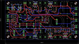
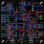
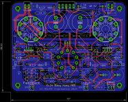
I put the schematic and the PCB in this message but it is still a work in progress therefor all remarks and/or suggestions are welcome... For info I made the PCB with the serigraph on the bottom side to facilitate the building
Rgds,
Marc
Looking at the schematic and PCB I’m not sure how you are making the connections with the CFB coils on the output transformer. Did I miss seeing the connections?
Marc, that is a very ambitious project! Good pla to go monoblock. I built a PPP kt88 stereo amp in 2001 and it weighs over 100lbs. I want to update that amp sometime soon, but it needs to get in line behind EL84 BH and possibly a balanced tube preamp.
When you build you should consider increasing your - bias supply above 100volts and also the current in the mosfet driver could be increased to help drive the extra capacitance and perhaps some grid current that may flow close to the 0 bias point. I find that I can see notches in the waveforms when driving high levels with the BH circuit with both el34 and KT88s due to the limiting of the bias supply and perhaps due to current limits. I noticed that even when I have notch free operation at the rated load impedance that the notches show up again if you lower the load impedance below the rated value.
I also found that the current sources in the output tube driver circuit were more linear when the 220k resistor was connected to the +bias supply (+22volts in my case) then when connected to the driver mosfet .
I am still fine tuning my BH and trying different operating points.
Hello Brian,
Yes, the Quad KT120 mono block will be about the weight of a stereo Baby Huey and that will be quite heavy already")
I will also need two power supply transformer therefor the dual mono is a logical solution. For the Vbias, you are right, I already found that and recommended to reduce R39 from 33k to 15k, or even 10k, for the EL34 version. The -75V on the PCB is a reminiscence of the Baby Huey design In fact for this amplifier I will have a dedicated power supply board that will use a small 115 V AC transformer giving about -150 V DC for the bias. I still have not decided if I will use the attached schema or use the 50 V AC output of the Toroidy power transformer for the +Vdriver and use bridge instead of a single rectifier ? As I said it's a design in evolution and the attached documents are not definitive and not checked, many resistor values could be modified because I am using the duplicate fonction during CAD work and I check values at the end...
Your remark about the current source is interesting, may be it can be an improvement for the new project ?
Rgds,
Marc
Yes, the Quad KT120 mono block will be about the weight of a stereo Baby Huey and that will be quite heavy already
I will also need two power supply transformer therefor the dual mono is a logical solution. For the Vbias, you are right, I already found that and recommended to reduce R39 from 33k to 15k, or even 10k, for the EL34 version. The -75V on the PCB is a reminiscence of the Baby Huey design
In fact for this amplifier I will have a dedicated power supply board that will use a small 115 V AC transformer giving about -150 V DC for the bias. I still have not decided if I will use the attached schema or use the 50 V AC output of the Toroidy power transformer for the +Vdriver and use bridge instead of a single rectifier ? As I said it's a design in evolution and the attached documents are not definitive and not checked, many resistor values could be modified because I am using the duplicate fonction during CAD work and I check values at the end...Your remark about the current source is interesting, may be it can be an improvement for the new project ?
Rgds,
Marc
Attachments
I find that I can see notches in the waveforms when driving high levels with the BH circuit with both el34 and KT88s due to the limiting of the bias supply and perhaps due to current limits. I noticed that even when I have notch free operation at the rated load impedance that the notches show up again if you lower the load impedance below the rated value.
I am still fine tuning my BH and trying different operating points.
Brian, If I remember correctly, you have increased you bias supply to ~ negative 90Vdc on your EL34/kT88 build. Did you see those notches in the waveform with the designed negative voltage ~_75Vdc, or also at the new -90Vdc?
Could you clarify “I noticed that even when I have notch free operation at the rated load impedance that the notches show up again if you lower the load impedance below the rated value.” How do you lower the load impedance; change transformers? Or do you mean changes in speaker impedance at different frequencies?
Thanks for sharing your experience. Please keep us less technically-gifted builders informed of the results of your fine tuning.
Yes, Francois lowering the load impedance, in this case a power resistor, to a value lower than the rated impedance of the output tap. Specifically, I put a 4 ohm load on the 8 ohm tap and I got the notches back again. You see them near the top and bottom of the waveform. A small dip in the sine wave but not clipping I think it is when the output tube that is being turned off has a clipped grid waveform due to running out of - swing. If your -bias supply is not high enough it will cause this problem. I need to think about why it comes back when the load resistance is lowered. Remember that I am pushing the driver to it’s limits with my setup.
I am currently working on finishing the case for the BH. Busy with multiple projects and income tax and house renovations and...... etc!
I am currently working on finishing the case for the BH. Busy with multiple projects and income tax and house renovations and...... etc!
Just a quick question I am running at over 400v (335v Xformer) and I see C5 drops from 100nf to 47nf, is this just because of the increase size of the cap? Or can I still use 100nf cap at 630v? I still haven't worked out how increase/decrease capacitance values affects the performance?
C5 is just a filtering capacitor in the C-R-C high voltage power supply, it is in paralleled with C6 an electrolytic capacitor of more than 100 uF therefor its value is not critical, it is just here to cancel somme possible high frequency noise
For C1 and C2 it is more critical because they are in the signal path and a lower value may reduce the bandwidth in the high frequency, if 630 V capacitors didn't fit in the space, you may put the capacitors under the PCB with longer wire...
Rgds,
Marc
For C1 and C2 it is more critical because they are in the signal path and a lower value may reduce the bandwidth in the high frequency, if 630 V capacitors didn't fit in the space, you may put the capacitors under the PCB with longer wire...
Rgds,
Marc
No, it is less critical for the voltage of these capacitors because C1 & C2 are connected to the anode of the 12AX7 which is normally between 150 V and 200 V, even if the negative voltage on the gate of the MOSFET can be -50 V you have still a good margin with 400 V capacitors
Rgds,
Marc
Rgds,
Marc
Attachments
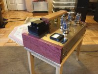
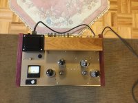
Almost finished BH
Been listening for a few weeks now off an on to BH with kt88 at 400v 68ma operating point Sounds real nice!! Driving it with an Aikido preamp.
I thought I should finish the regulator enclosure and add side panels to cover the high voltage bits and make it look like more of an amp and less of a science project. Still have a piece of trim to go on the lower front to hide the joint between top and bottom of the case. I’d also like to get a name plate engraved and also a plate with switch labels.
Here are a few pictures.
Attachments
-
 2CD379E5-04E0-4227-8BE6-903B3CFC6778.jpeg258.8 KB · Views: 706
 -
 531F9C12-21B6-48B1-9321-67BE7D1BA2F8.jpeg230.8 KB · Views: 771
 -
 259032A4-60AC-4801-8BDE-5678B69810FF.jpeg239.8 KB · Views: 777
 -
 88FBF9CD-0494-46BA-8A95-028629DF8F87.jpeg258.9 KB · Views: 760
 -
 2F8EC066-069E-493F-BD24-23E20C3CC586.jpeg235.4 KB · Views: 796
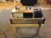
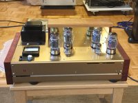
Thank You for the complements Philippe and Silasmellor! The output transformers are not in the wooden box on top of the chassis. I have HV and bias regulators mounted inside hat box and the 2 heatsinks are for those boards. The black one is for HV and the silver one for bias supply. They also form the back side of the box.
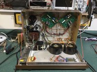
The Toroidy output transformers are mounted to the inside bottom of the chassis. I am attaching a photo of an earlier stage of the build with the hood up!
It makes it a lot easier to do the bias with that meter. The silver rotary switch in front of the meter allows me to select the tube I am biasing. It has an off position as well. The little black switch changes meter ranges from 50ma for EL34 etc. to 100ma for kt88/6550.
Attachments
Here are a few pictures.
Thanks for sharing your pictures. It's very rare to find different approach on assembling amplifiers specially bought on GB.
I'm curious to know couple things:
- You're using KT88, have you measure power out in 8 ohms,
- What HV regulator you're using.
Many thanks,
bekim
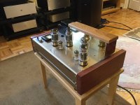
Hello Bfpca,
Very nice built indeed, I like it Good idea to put a mirror like plate behind the tubes, it must be very beautiful in the dark ! It look already like a real amplifier, when my amplifier look like a science project that mean that the PCB are just on a piece of wood with plenty of wire everywhere
I am also very happy that you like the sound, I was not sure that a PCB version will be so good as many people who built tubes amplifier said that point to point wiring was the best solution
Since I started the design of the PCB for the Baby Huey I have learned a lot of things about tubes amplifier, and at the beginning I have just made the simplest possible PCB based on the EL84 and EL34 project of Ian (gingertube) I didn't expected that more of 500 PCB will be bought and hopefully will be built !
After this experience and based on a lot of feedback, I am thinking to make a new version with a separate power supply board and some very limited changes, however I will keep exactly the same dimensions if some one want to retrofit his own amplifier... In a previous post you have said that you connected the MOSFET current source directly to the +V driver, did you find that the sound was better this way ? The new power supply board will be optimized for the Toroidy TSA 250/001 (https://www.tme.eu/Document/57008aa91b6cc754bad025ca3e7a413f/TSTA-TOROIDY-EN.pdf) and following your comments about Vbias, I will use a doubler on the 50 V AC to get more that 100 V to bias KT88 like tubes ! More details and schematic soon...
Cheers,
Marc
Very nice built indeed, I like it
Good idea to put a mirror like plate behind the tubes, it must be very beautiful in the dark ! It look already like a real amplifier, when my amplifier look like a science project that mean that the PCB are just on a piece of wood with plenty of wire everywhere I am also very happy that you like the sound, I was not sure that a PCB version will be so good as many people who built tubes amplifier said that point to point wiring was the best solution
Since I started the design of the PCB for the Baby Huey I have learned a lot of things about tubes amplifier, and at the beginning I have just made the simplest possible PCB based on the EL84 and EL34 project of Ian (gingertube) I didn't expected that more of 500 PCB will be bought and hopefully will be built !
After this experience and based on a lot of feedback, I am thinking to make a new version with a separate power supply board and some very limited changes, however I will keep exactly the same dimensions if some one want to retrofit his own amplifier... In a previous post you have said that you connected the MOSFET current source directly to the +V driver, did you find that the sound was better this way ? The new power supply board will be optimized for the Toroidy TSA 250/001 (https://www.tme.eu/Document/57008aa91b6cc754bad025ca3e7a413f/TSTA-TOROIDY-EN.pdf) and following your comments about Vbias, I will use a doubler on the 50 V AC to get more that 100 V to bias KT88 like tubes ! More details and schematic soon...
Cheers,
Marc
Baby Huey MK2
Hi,
As I have announced in the previous post, I have started the design of two new PCB for a second generation of the EL34 Baby Huey taking advantage of all suggestions, remarks and criticism of the first one
For this new version I have separated completely the audio board and the power supply board to avoid all possible 50/60 Hz AC noise on the amplifier section. Based on the picture of several builders I have also made a reversed PCB where the serigraph is viewed from the bottom, therefor it is more easy to mount nearly all components on the bottom of the PCB with only the tubes and the trimmer on the top...
I keep the same dimension and tubes location therefor it will be possible tu use existing enclosure and many expensive parts like tubes ! It is still a work in progress therefor all suggestion are welcome
Cheers,
Marc
Attachments
- Home
- Amplifiers
- Tubes / Valves
- EL34 Baby Huey Amplifier