So what are you telling me Marc? Not to ask you guys where to get some items? I was told to go to this post for help on making these boards and ask these type of questions. If it’s above you to answer something for me that’s find. Just don’t say anythingHi carlthess40,
The last BOM fort BOTH EL34 Baby Huey & EL84 Baby Huey is in post 198 ! This is a forum for DIY fans, it is not a hot line for a Company selling expensive kit like Heathkit in the past, PCB are produced without profit and schematic or layout are done for free, but it is expected that people buying PCB will work a little bit to find the parts and buy them..
If I’m reading you wrong then sorry. But you commit did sound like I was out of line in asking about where to get the bulk of the parts
Hi Carlthess40,
Marc had done a marvelous job for all of us with the PCB design (thanks again Marc), but he has been answering some of the same question many times over. Lets give Marc a break. The rest of us should help out with questions and discussion.
What Marc is implying is that we, the current batch of builders should do our homework and read previous Baby Huey threads, study the schematic against the latest BOM he posted in #198, etc. There is no kit or group buy for parts - that is the DIY fun to select your own super-duper parts. Apologies if I misunderstood you, Marc.
Hello Carl,
I am posting this on behalf of Marc before he becomes too angry
To do justice to DIY spirit, I did request you to read the build thread (in entirety) and then post your specific questions if you had any. GB for Baby Huey PCB
You see, this is a pure diy activity, where Marc did all the designing and I modified PCB design a bit and agreed to help Marc with PCB manufacturing and conducting the GB myself. He is a good friend of mine.
There are risks involved, with any DIY as you might already be knowing.
I sincerely hope you and every subscriber take Marc's comments in positive spirit and spend some time planning the build based on info already posted here in the thread.
Regards
Prasi
Last edited:
Nice looking work Bfpca. Yup, there is some exploration and homework to be done in DIY, as the name implies. And one should thoroughly read the threads before asking the designer questions. But let's all be civil and kind.
First, just got my boards and they look terrific in quality and in thoroughness. Impressive layout and detail in parts identification.
As to key questions or issues, the Baby Huey EL34 build thread lists most answers one would need, and I have been studying it. The key decision points for us DIYers, especially those "not so expert tube amp builders," (as I see it) are: 1) Power transformer choice: the identified toroid seems the most complete, all in one shopping choice. Or one can cobble several different transformers or power sources into the build, which will take up more space and wire routing and be more complex for a newer DIYer. The toroid can be had in Europe for around $100 plus shipping. Good deal. It has secondary voltages for the main power supply, the 50-60 watt power supply, and the filament heater supplies. 2) Tube filaments (heater) power: One can power directly with AC voltage from the transformer, which may induce some hum, or rectify and regulate for DC, which theoretically will be more quiet. This regulation can be done through an inexpensive "buck" converter which one cold build or just source from eBay for $7. Builder's choice. The toroid transformer, and most other power transformers, will have the heater secondary wires built in. Most transformers will not have a 50-60 watt secondary. Thus you may need to source that and could use a simple switch mode power supply (SMPS). 3) Choke or Not: You can substitute a choke in place of one resistor in the power supply to potentially provide better filtering (things look pretty good as they are). Or you can build without a choke and easily add later if you want to see if there is any sound improvement. You are talking about two solder connections and the cost of the choke. Choke may run you $20. 4) As to the power supply, all rectification and filtering is done on the board, so you do not need an extra power supply board, just input the secondary voltage from the transformer(s). As indicated in bullet point 2, no rectification or filtering is supplied on the filament heater inputs. If you want DC instead of AC (which will work), you need to provide for that. I think those are the main points. Also, if a newbie, be careful as the design will run up to 400 volts in the B+ supply, more than enough to kill. And a dead DIYer is going to miss out on some really good tube sound. If one is concerned about such a voltage level and prodding around with a multimeter to test it, then look at the build thread that talks about inserting a digital volt meter in the B+ circuit. Also, any amplifier build must include an appropriate fuse in the mains input placed prior to your on/off switch.
Kudos to our two fellow DIYers for designing such a great amplifier and for offering it in such an excellent and in-expensive PCB. Part of the joy of DIY is the camaraderie, sharing and communication within the community. I am going to thoroughly enjoy this project! Thanks, all!!
Last edited:
Prasi
Thanks for all of your help. I have been trying to read all the different post. This build
Has branched out into a few post and it’s somewhat hard for a newbie like myself to keep up with what is going on
I only asked a simple question. One that I’m no way warranted a response like I received from Marc. I know he has put in countless hours like you and others have and I say a big thank you to you guys. This still does not warrant a response like that
I did get a fast and helpful response to my question that I was looking for, I feel Marc should have just sent me a message if he has a problem with me or my questions
As of now if this is how me or others will be treated , then count me out of this
I will just list these two great boards up for sale and stay out of Marc’s way
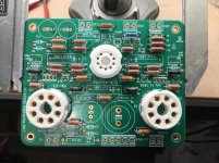
I have gotten a start on the BH 34 build. I have put in most of the resistors and the sockets. These boards are very nice to work with.
Here is a photo of the progress.
hello Bfpca,
that's a nice looking build. and also the jig seems very useful. Is it custom made or commercially available?
regards
Prasi
Hi Francois & Prasi,
Thank you for your comments
I appreciate that you understand fully my point of view about DIY activity. I don't know why Carl is upset about my answer, even if English is not my Mother language, I don't think my words were aggressive, I have just explained that this was not a Group Buy for a full kit with all part available, but a simple PCB and there was also a BOM with part references and suggested Mouser purchase references to help builders to get the parts easily
More than 500 EL34 and EL84 Baby Huey PCB have been sold, and all the builders who finished it enjoyed the quality of the sound of this amplifier using an uncommon design with the shunt feedback and no need for a global feedback ! Again, this is not my design, this was done by Ian (gingertube) who started the EL84 Baby Huey thread in January 2006. when I found this subject in October 2016 (10 years later) it was my first post on this forum : post 1670 ( EL84 Amp - Baby Huey ) nearly all the Baby Huey were built with point to point wiring Since I am not good in this method, I have decided to draw a PCB... To make it even easier to build, I decided to put ALL components on board, including the power supply, therefor to finalise a complete amplifier only the power and output transformers were needed outside of the PCB
I have made a ECL86 and a EL84 Baby Huey PCB. Later, I have made a EL34 version with the help of Ian who had modified commercial tube amplifiers with EL34 output tubes... After two Group Buy (200 PCB sold) I asked Prasi if he would be kind enough to manage this very time consuming activity ! He has sold 200 more EL34 BH PCB and since some people were interested to build the EL84 version, I didn't use the first prototype PCB but I have modified the EL34 version which was better designed to replace octal sockets by noval 9-pin ones and 100 EL84 boards were made by Prasi...
This approach interested many builders who had never made a tube amplifier before who enjoyed it a lot. I understand that Carl want to sell his boards, that will make someone happy I have no problem with him but may be he is a little too susceptible ?
Best regards,
Marc
Thank you for your comments
I appreciate that you understand fully my point of view about DIY activity. I don't know why Carl is upset about my answer, even if English is not my Mother language, I don't think my words were aggressive, I have just explained that this was not a Group Buy for a full kit with all part available, but a simple PCB and there was also a BOM with part references and suggested Mouser purchase references to help builders to get the parts easily
More than 500 EL34 and EL84 Baby Huey PCB have been sold, and all the builders who finished it enjoyed the quality of the sound of this amplifier using an uncommon design with the shunt feedback and no need for a global feedback ! Again, this is not my design, this was done by Ian (gingertube) who started the EL84 Baby Huey thread in January 2006. when I found this subject in October 2016 (10 years later) it was my first post on this forum : post 1670 ( EL84 Amp - Baby Huey ) nearly all the Baby Huey were built with point to point wiring
Since I am not good in this method, I have decided to draw a PCB... To make it even easier to build, I decided to put ALL components on board, including the power supply, therefor to finalise a complete amplifier only the power and output transformers were needed outside of the PCB I have made a ECL86 and a EL84 Baby Huey PCB. Later, I have made a EL34 version with the help of Ian who had modified commercial tube amplifiers with EL34 output tubes... After two Group Buy (200 PCB sold) I asked Prasi if he would be kind enough to manage this very time consuming activity ! He has sold 200 more EL34 BH PCB and since some people were interested to build the EL84 version, I didn't use the first prototype PCB but I have modified the EL34 version which was better designed to replace octal sockets by noval 9-pin ones and 100 EL84 boards were made by Prasi...
This approach interested many builders who had never made a tube amplifier before who enjoyed it a lot. I understand that Carl want to sell his boards, that will make someone happy
I have no problem with him but may be he is a little too susceptible ? Best regards,
Marc
hello Bfpca,
that's a nice looking build. and also the jig seems very useful. Is it custom made or commercially available?
regards
Prasi
Thank You Prasi. The jig is an ancient Panavise. The one I am using is purpose built to hold circuit boards for assembly.
The company still exists - PanaVise Products, Inc.
I appreciate all the concerns from new diy builders with regards to parts selection etc. I think it would be good for more experienced builders to document their builds in the build thread giving as much info about parts choice as they can. I will attempt to do that as I proceed, starting with testing a single board to look at B+ versus power output etc.
For power supply simulations the Duncan Amps PSUD utility is something that is a great learning tool and can get you very close to what you need for building a tube amp supply.
Info on PSUD PSUD2
Hi kp93300,
As meanie said, the heater connection are not tied to GND There is no capacitor either since these lines can be powered in DC or in AC.
You must not change the LED color because the forward voltage drop of the LED define the current in the input stage ( LED Resistor Calculator ), with a red LED it is 1.8 V, if you are using a blue LED by example it will be 3.4 V
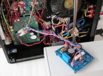
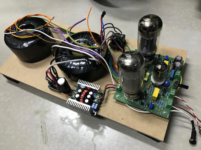
As several builders like analogadikt and kolakidd have requested if it was possible to connect a power transformer with middle connection or if it is possible to add an external rectifier and a bigger filtering, I have made the test (see picture) to find if there was some improvement, and the answer is YES, it reduce even more the hum if there was some
I have used a PS-3 HV board kindly sent to me by cambe, but a simple rectifier bridge and a R-C filter can do the job.
Rgds,
Marc
As meanie said, the heater connection are not tied to GND
There is no capacitor either since these lines can be powered in DC or in AC.You must not change the LED color because the forward voltage drop of the LED define the current in the input stage ( LED Resistor Calculator ), with a red LED it is 1.8 V, if you are using a blue LED by example it will be 3.4 V
As several builders like analogadikt and kolakidd have requested if it was possible to connect a power transformer with middle connection or if it is possible to add an external rectifier and a bigger filtering, I have made the test (see picture) to find if there was some improvement, and the answer is YES, it reduce even more the hum if there was some
I have used a PS-3 HV board kindly sent to me by cambe, but a simple rectifier bridge and a R-C filter can do the job.
Rgds,
Marc
Attachments
Hello Hope this is the right post for this If you ordered the mouser GB parts list and have the 10 green two pin fixed terminal blocks And you are waiting on the back order for them, as they will not be in Stock until early August . You can substitute for this part number that’s in the picture , the top line shows the original part number the bottom line with the red checkmark is the new part number that they have in stock now , it’s just a few more pennies per item but they can at least ship it out today I hope this helps out , if this is the wrong place to post this , sorry Then if the moderator could please move it to the proper post I would appreciate that

Last edited:
Good Day !
@Fabian85, I m using 6.6kohms impedance for my EL34/6CA7 Shuguang matched quads. It drives my Mistral 3/5A wonderfully.
@kp93300, you may want to use a choke/inductor in place of R27, it may smoothen your suppy rail voltage ripples. As for hum, i have tried both AC and DC heating, the DC does improves very slight over the direct AC heating, but that's in my case, it may varies case to case on hum troubleshooting.
Having external bridge rectifier and bigger reservoir caps is a plus point...But as of the current design is already a very good for a valve amp point of view.
Fix them up quick and start enjoying music !
An externally hosted image should be here but it was not working when we last tested it.
- Home
- Amplifiers
- Tubes / Valves
- EL34 Baby Huey Amplifier