Hello, I am sorry if this is obvious, it is my first serious attempt to make a tube amplifier. Is there a need for OT protection? What would happen if a speaker was disconnected or shorted?
With no speaker load, high voltages are generated in the primary windings as the magnetic field collapses in the O/P transformer and the energy released has nowhere else to go. This can produce internal arcing in the O/P valves which may or may not survive. The answer is to make sure your speaker is always firmly connected! By way of simple protection, you can connect a resistor across the O/P (in parallel with the speaker). The lower the resistance, the better the protection but the more power is wasted. I have seen 1k used - 125x the resistance of an 8 ohm speaker, therefore negligible power loss.
Silly question but I am having a hard time envisioning how the signal gets to the other half of the 12ax7 if no feedback is employed...can someone enlighten me?
The constant current source supplying both cathodes of the 12AX7 supplies 2.5mA, that is 1.25mA per individual triode. If the I/P goes high (+ve) V1a will demand more current but only 2.5mA total is available, so V1b current will reduce proportionally. Therefore the anode volts at V1a will decrease while that at V1b increases by the same amount. This arrangement is called a long tailed pair.
I'm keen on building this as I have some suitable Edcor OTP's 4.2K 60W
I just wanted to check though because I have two Hammond 290FX transformers on hand, and it would be great if I didn't need to order new ones:
320 0 60 320 @ 518mA
6.5V @ 5.5A
Is the 320V going to be way high for this amp, even with the 500V caps?
I would ignore the 6.5V and use the buck boost module.
With 500v caps and pushing it to the max you are good to 350vac with a basic ss rectifier and c filter. You need to check the open circuit voltage for your 290fx. Unless you are going to delay the B+, the filter caps will be subjected to the full unloaded output voltage until the tubes heat enough to draw current. Once you get past the warm up then you have a defined operating point at which you can somewhat fine tune the B+ by using a CLC or CRC filter to lower it a bit. A tube rectifier is another way to delay and lower the B+ a bit. You would choose a rectifier with a slow turn on and enough current capability for the job. Within those specs there will likely be some choices with different voltage drops to allow some fine tuning of B+. 60volts should work for the bias supply so the 290fx looks good for this application at least from the basic specs you have provided.
The other issue is the operating point at a high B+. You will need to have a higher negative bias and more drive voltage to get full power. A lot depends on your choice of tubes. You could always use some sort of regulation or a cap multiplier with a series mosfet to lower B+ as another option.
The other issue is the operating point at a high B+. You will need to have a higher negative bias and more drive voltage to get full power. A lot depends on your choice of tubes. You could always use some sort of regulation or a cap multiplier with a series mosfet to lower B+ as another option.
Last edited:
Ahhh ok so with the outputs coming off both anodes if the feedback is employed it gets injected into the grid of v1b thus attenuating the signal?
If you are familiar with op amp circuit models, think of it as a non inverting op amp with the 2 grids of the input tube acting as the +and - inputs. Then you can see that a resistor, or resistor/cap combination, from the output to the - input, along with a second resistor to ground will define the gain of the amplifier. This is a very basic explanation but may help to frame the circuit in familiar SS terms.
So the feedback 1 input on the diagram would go to the output transformer+ Speaker output and the feedback 0 would go to the -output.
kolakidd, I have built several amps using the Hammond 290fx. Some of those amps were EL34's. It is a great value in my opinion. I have used 500v caps on the filters with no problems. I would definately use the 290fx for this application. Under quiescent conditions, expect about 420vdc at the first filter cap.
Hi Marc ,
I will try this HB connected as EL34 triode mode, so i will change R14 and 15 to 100R , then the PCB's output-1 short to 2 and output-5 short to 4.
Am i correct to this modification ? Any advice and regarding points need to pay attention ?
My power transformer B+ is 330VAC (will use TSTA 0250/001) so in this triode mode connection, estimate how much power can be delivered ?
Find in earlier discussion about the bias problem , should i change the R39 to 10K~5K ?
Hope to have your comment :>
CK
One check to make before you connect the feedback loop and install the output tubes is to check the -bias voltage available at the grids of the output tubes. You can run the adjustments from end to end and note the range you get. To me it seems convenient to change those resistors to something lower right at the start. You will always be able to get a low enough bias voltage (about-4v minimum) for any of the targeted output tubes but not necessarily high enough if you decide to try kt88 etc.
I've finished populating the boards... but I'm having "connection anxiety" with the 290FEX, I don't really feel like toasting anything. I've done a basic drawing of how I see it connecting, but I just wanted to get confirmation.
If I have it wrong, I will redraw and re-post correctly.
If I have it wrong, I will redraw and re-post correctly.
Attachments
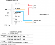
WARNING DANGER!
You MUST NOT connect your transformer this way
The on board rectifier is a bridge, if you connect the Baby Huey like that you will have 600 V AC on tha AC input !!! It is far too much.
If you are using a transformer with 2 x 300 V output you must use two external diodes to feed the BH with about 420 V DC (with 500 V capacitors) !
Don't connect your EL34 Baby Huey like on your schematic, you will destroy it
Rgds,
Marc
Thank you, seriously! Completely understood. Nothing is connected yet, and yes the board is populated with 500v Caps.
I'm basically trying to figure out the optimal way to use the 290FEX. I may just have to revert to another transformer. What I think you're saying is bypass the PCB bridge and use a Full Wave CT bridge.
I'm basically trying to figure out the optimal way to use the 290FEX. I may just have to revert to another transformer. What I think you're saying is bypass the PCB bridge and use a Full Wave CT bridge.
You don't need to remove the on board diodes, they will protect your module in case of wrong connection
You can refer to the following document to connect your Baby Huey : Design Guide For Rectifier Use - Hammond Mfg. In your case you can use the "Full Wave Resistive Load" schema !
It is better to add an external capacitor for a good filtering...
Or you can use a transformer like the Toroidy TSTA250-001 that include all the voltages for the EL34 Baby Huey : TSTA 250/001 TOROIDY - Transformer: toroidal audio | TME - Electronic components
Good luck,
Marc
Hi Marc and all,
I want to use individual DC buck converters for each channel like Marc recommended here.
I'm doing it to isolate the PS between channels as much as possible, using individual 0-275@100ma as well.
Will this be ok ? Is this a wasted exercise ?
Thanks,
Sunil
I want to use individual DC buck converters for each channel like Marc recommended here.
I'm doing it to isolate the PS between channels as much as possible, using individual 0-275@100ma as well.
Will this be ok ? Is this a wasted exercise ?
Thanks,
Sunil
Hi Sunil,
Except if you want to make mono blocs, it is useless to separate power supply for each channel and if you do that you should also separate 50 V AC power supply because one of the line is connected to ground !
As you say it's a waste of time and money
Regards,
Marc
Except if you want to make mono blocs, it is useless to separate power supply for each channel and if you do that you should also separate 50 V AC power supply because one of the line is connected to ground !
As you say it's a waste of time and money
Regards,
Marc
- Home
- Amplifiers
- Tubes / Valves
- EL34 Baby Huey Amplifier