Yes, I don’t have the file right here in front of me but I have regulated B+ that is adjustable and set to 300. I monitored the screen current during the biasing of the amp and to stay under the screen dissipation limit I had to stay below 30-32ma plate current. Now, I am running the Toroidy transformers which have lower dc resistance and voltage drop then an EI transformer so screen and plate net voltages are slightly higher than typical. You could probably push those tubes right up to and maybe slightly beyond the limits on the screen but I didn’t feel the need for the extra power. They are after all Russian military tubes. The difference between 11w and 15 didn’t seem worth it in my situation.
I have not had a chance to try EL84. I have a bunch of used 6BQ5 and out of about 20 there are 2 reasonable pairs that I could try to use. I did run one pair of 6BQ5 during testing and got a bit more power. Distortion and output impedance were similar. The screen power dissipation limits are quite a bit higher on EL84.
Decware uses the 6P15 in their low powered amps and believe they are good sounding tubes. My time with the BH verified that.
Decware uses the 6P15 in their low powered amps and believe they are good sounding tubes. My time with the BH verified that.
I've noticed that the PI has not enough gain for big bottles like KT88.
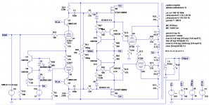
If someone want to test it with his own amp, I propose the mod in attachment to increase the gain of the PI and be able to reach 60 Wrms with the following THD:
If someone want to test it with his own amp, I propose the mod in attachment to increase the gain of the PI and be able to reach 60 Wrms with the following THD:
Code:
Harmonic	Frequency	 Fourier 	Normalized	 Phase  	Normalized
 Number 	  [Hz]   	Component	 Component	[degree]	Phase [deg]
    1   	1.000e+03	3.087e+01	1.000e+00	   -0.53°	    0.00°
    2   	2.000e+03	3.138e-02	1.017e-03	  109.92°	  110.45°
    3   	3.000e+03	2.731e-01	8.847e-03	   -4.08°	   -3.55°
    4   	4.000e+03	2.279e-02	7.384e-04	  -75.96°	  -75.43°
    5   	5.000e+03	8.824e-03	2.859e-04	 -172.31°	 -171.78°
    6   	6.000e+03	7.115e-03	2.305e-04	   87.09°	   87.62°
    7   	7.000e+03	4.841e-03	1.568e-04	   78.36°	   78.89°
    8   	8.000e+03	4.109e-04	1.331e-05	 -116.51°	 -115.98°
    9   	9.000e+03	1.959e-03	6.346e-05	 -152.42°	 -151.89°
Total Harmonic Distortion: 0.894467%(0.894470%)
Attachments
This is a preliminary version with KT120, obtaining the following results at 85 Wrms:
Code:
Harmonic	Frequency	 Fourier 	Normalized	 Phase  	Normalized
 Number 	  [Hz]   	Component	 Component	[degree]	Phase [deg]
    1   	1.000e+03	3.686e+01	1.000e+00	   -0.51°	    0.00°
    2   	2.000e+03	9.090e-02	2.466e-03	   97.40°	   97.91°
    3   	3.000e+03	4.455e-01	1.209e-02	   -0.32°	    0.19°
    4   	4.000e+03	5.228e-02	1.418e-03	  -85.01°	  -84.51°
    5   	5.000e+03	7.115e-02	1.930e-03	 -165.22°	 -164.71°
    6   	6.000e+03	1.146e-02	3.109e-04	   85.69°	   86.20°
    7   	7.000e+03	3.178e-02	8.621e-04	   14.60°	   15.11°
    8   	8.000e+03	2.485e-03	6.742e-05	  -89.24°	  -88.74°
    9   	9.000e+03	8.774e-03	2.380e-04	 -174.69°	 -174.18°
Total Harmonic Distortion: 1.260178%(1.260207%)
Attachments
Optimized KT88 schematic at 75 Wrms:
Code:
Harmonic	Frequency	 Fourier 	Normalized	 Phase  	Normalized
 Number 	  [Hz]   	Component	 Component	[degree]	Phase [deg]
    1   	1.000e+03	3.473e+01	1.000e+00	   -0.49°	    0.00°
    2   	2.000e+03	1.481e-02	4.264e-04	  168.50°	  168.99°
    3   	3.000e+03	3.245e-01	9.343e-03	   -7.06°	   -6.57°
    4   	4.000e+03	1.624e-02	4.675e-04	  -68.55°	  -68.06°
    5   	5.000e+03	1.288e-02	3.707e-04	 -128.16°	 -127.67°
    6   	6.000e+03	9.153e-03	2.635e-04	   87.47°	   87.97°
    7   	7.000e+03	1.914e-02	5.511e-04	   70.55°	   71.04°
    8   	8.000e+03	4.303e-03	1.239e-04	 -122.63°	 -122.13°
    9   	9.000e+03	9.785e-03	2.817e-04	 -130.55°	 -130.06°
Total Harmonic Distortion: 0.939632%(0.939845%)
Attachments
I'm thinking about using two of my already populated EL84 boards to build a KT88 version (with off board tubes, of course).
I've read this post: EL34 Baby Huey Amplifier
explaining the reasons of the external supply, and I will use chassis mounted supply e-caps rated for 500-550 V.
I've simplified the previous circuit in order to keep the pcb as original as possible:

Output transformers based on this one: TTG-KT88PP - Tube output transformer [4kOhm] 2xKT88 / 2x300B Push-pull or similar - Shop Toroidy.pl but with 20% UL taps and 400 mArms maximum.
THD at 85 Wrms is as follows:
I've read this post: EL34 Baby Huey Amplifier
explaining the reasons of the external supply, and I will use chassis mounted supply e-caps rated for 500-550 V.
I've simplified the previous circuit in order to keep the pcb as original as possible:
Output transformers based on this one: TTG-KT88PP - Tube output transformer [4kOhm] 2xKT88 / 2x300B Push-pull or similar - Shop Toroidy.pl but with 20% UL taps and 400 mArms maximum.
THD at 85 Wrms is as follows:
Code:
Harmonic	Frequency	 Fourier 	Normalized	 Phase  	Normalized
 Number 	  [Hz]   	Component	 Component	[degree]	Phase [deg]
    1   	1.000e+03	3.684e+01	1.000e+00	   -1.64°	    0.00°
    2   	2.000e+03	1.217e-02	3.303e-04	  -88.97°	  -87.33°
    3   	3.000e+03	1.156e+00	3.137e-02	   -5.64°	   -4.00°
    4   	4.000e+03	1.859e-03	5.047e-05	   88.86°	   90.50°
    5   	5.000e+03	2.799e-01	7.597e-03	 -178.62°	 -176.98°
    6   	6.000e+03	4.094e-04	1.111e-05	 -107.17°	 -105.53°
    7   	7.000e+03	6.444e-02	1.749e-03	   -6.08°	   -4.44°
    8   	8.000e+03	7.026e-05	1.907e-06	  -33.75°	  -32.11°
    9   	9.000e+03	4.134e-03	1.122e-04	  126.24°	  127.87°
Total Harmonic Distortion: 3.232980%(3.233033%)
Attachments
I've applied the feedback system I have in my other amp inspired by the RCA50W, and I obtain more power, mainly 3H with the possibility to adjust the 2nd by changing one of the two feedbacks from anode to grid of the PI.
This is at 90 Wrms:
This is at 90 Wrms:
Code:
Harmonic	Frequency	 Fourier 	Normalized	 Phase  	Normalized
 Number 	  [Hz]   	Component	 Component	[degree]	Phase [deg]
    1   	1.000e+03	3.800e+01	1.000e+00	   -1.12°	    0.00°
    2   	2.000e+03	3.120e-03	8.209e-05	   89.52°	   90.64°
    3   	3.000e+03	1.450e+00	3.816e-02	   -6.19°	   -5.07°
    4   	4.000e+03	6.913e-03	1.819e-04	  109.46°	  110.58°
    5   	5.000e+03	1.956e-01	5.147e-03	 -151.48°	 -150.36°
    6   	6.000e+03	6.829e-03	1.797e-04	 -102.20°	 -101.07°
    7   	7.000e+03	2.056e-01	5.411e-03	    0.89°	    2.02°
    8   	8.000e+03	3.579e-03	9.418e-05	   77.36°	   78.49°
    9   	9.000e+03	8.915e-02	2.346e-03	  154.55°	  155.68°
Total Harmonic Distortion: 3.895504%(3.898309%)
Attachments
Two thinks to do maybe :
1) Instead of the 12AX7, it could be a better idea to use an high gm tube like the ECC88 (or at least a 12AT7 ?) with around 3-5ma cathode current and a plate voltage around 100v and a lower plate resistor.
2) Verife if the source current is justified for the two mos drivers. Maybe a simple resistor will not change the results alot.
3) By the way, the plate resistors could be bootstrapped by the the common source Mos ampliers.
Charles
Bonjour Charles,
1) the 12ax7 has the right current to permit not to load too much the primary of the OT (47k + 15k + 47k = 109k = 14 times Raa)
1bis) 5 mA will need 5 times less plate resistor, and a huge waste of power
2) the first version of the BH had resistors instead of CCS for the powerdrive, and results were worse (done myself too)
3) Mosfets do not amplify, the are source followers with unity gain.
I'm thinking about using two of my already populated EL84 boards to build a KT88 version (with off board tubes, of course).
<snip>
I've simplified the previous circuit in order to keep the pcb as original as possible:
<snip>
Output transformers based on this one ... but with 20% UL taps and 400 mArms maximum.
Roberto, all very interesting! I have a couple of questions:
1. Your schematic does not show the on-board bias adjust - is that merely for simplicity of simulation? If not why do away with the bias adjust?
2. Why and how much is this custom 20% UL Toroidy better than the standard 40% UL KTT-KT88PP? And how many more €s for the custom transformer? I know old application sheets show EL84’s to have better performance with 20-25% UL screen taps, but I had never seen the same for KT88, EL34 etc.
Last edited:
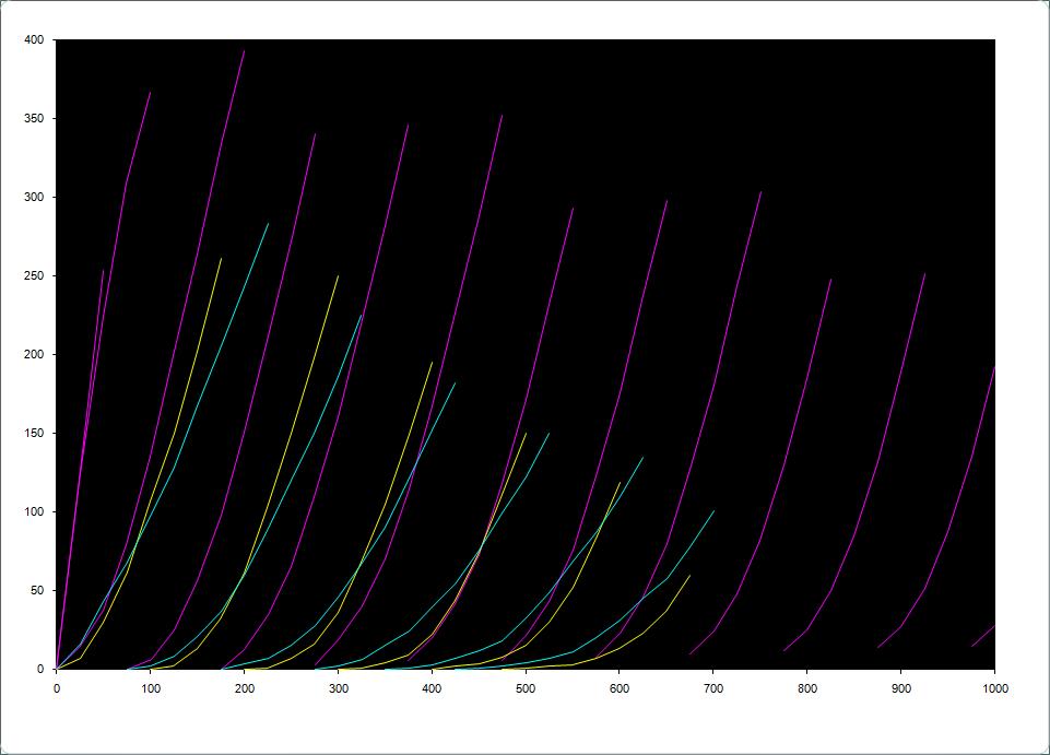
Francois, you can find data of the KT88 in the old GEC datasheet at page 10:
https://frank.pocnet.net/sheets/084/k/KT88_GEC.pdf
Internal resistance of the tube is 12 kOhm in pentode mode, 670 Ohm in triode mode as per initial informations, even if the plot at page 10 suggests around 20 kOhm in pentode, 6.1 kOhm at 25%UL, 4.2 kOhm at 40%UL, 2.3 kOhm in triode. The values of the plot seems not realistics, as an EL84 has around 2 kOhm in triode and an EL34 around 910 Ohm.
But looking at the shape of the plot, it follows the behaviour of all other tubes (Hafler and Keroes docent), where the major difference in internal resistance is in the first 20% of the UL, then there's a light improvement up to triode configuration, power is constant from around 20 to 40% but the tube is easier to be driven at 20%. This is with UL only.
In the BH we apply also anode-to-grid local feedback, and it alone can perfectly triodize the curves (here you can see a KT88 with fixed "tetrode/pentode" voltage on g2 and 20% local feedback vs 300B curves: Local feedback between grid-cathode)
 .
.
In our case a 20% lnfb would be 22k instead of 33k for the local feedback resistor (11k/58k = 19%). By using a bit of UL, the lnfb can be reduced.
Less UL means also (based on simulations) a g1=0 curves moved towards the left, so more available power. Less lnfb and less UL means less stress on the PI, but a lower DF.
With EL84s I'm very happy with 23%UL + 14%lnfb (15k instead of 16.5k).
Damping is quite low, but the overall balance is IMHO very good.
Another option is four KT77 per side, instead of two KT88. They are very linear in UL, like EL84. And easier to drive than the KT88.
https://frank.pocnet.net/sheets/084/k/KT88_GEC.pdf
Internal resistance of the tube is 12 kOhm in pentode mode, 670 Ohm in triode mode as per initial informations, even if the plot at page 10 suggests around 20 kOhm in pentode, 6.1 kOhm at 25%UL, 4.2 kOhm at 40%UL, 2.3 kOhm in triode. The values of the plot seems not realistics, as an EL84 has around 2 kOhm in triode and an EL34 around 910 Ohm.
But looking at the shape of the plot, it follows the behaviour of all other tubes (Hafler and Keroes docent), where the major difference in internal resistance is in the first 20% of the UL, then there's a light improvement up to triode configuration, power is constant from around 20 to 40% but the tube is easier to be driven at 20%. This is with UL only.
In the BH we apply also anode-to-grid local feedback, and it alone can perfectly triodize the curves (here you can see a KT88 with fixed "tetrode/pentode" voltage on g2 and 20% local feedback vs 300B curves: Local feedback between grid-cathode)
In our case a 20% lnfb would be 22k instead of 33k for the local feedback resistor (11k/58k = 19%). By using a bit of UL, the lnfb can be reduced.
Less UL means also (based on simulations) a g1=0 curves moved towards the left, so more available power. Less lnfb and less UL means less stress on the PI, but a lower DF.
With EL84s I'm very happy with 23%UL + 14%lnfb (15k instead of 16.5k).
Damping is quite low, but the overall balance is IMHO very good.
Another option is four KT77 per side, instead of two KT88. They are very linear in UL, like EL84. And easier to drive than the KT88.
I'm ordering the transformers from Toroidy for a 6550 or KT88 amp.
460V B+, -140 to +50V for the drivers
4kRaa with 23% UL taps (it simulates very similar to my EL84 version in terms of harmonic ratios).
Q1, Q7 and Q9 substitued with MJE340 that have a safer Vce of 300V ( https://www.mouser.it/datasheet/2/389/cd00000930-1795564.pdf ).
C1, C2 and C5 now rated at 630V
C6 and C7 offboard with multiple 220uF 500V
C10 now rated at 200V, C11 is ok like that.
Last edited:
- Home
- Amplifiers
- Tubes / Valves
- EL34 Baby Huey Amplifier