Hello;
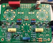
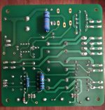
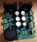
Here are some pictures of the beginning of the construction of the maps. The resistors R43 and R44 have been replaced by resistors 1w 500v the 2w had trouble entering, Ian do you think that the power dissipation level of the 1w is sufficient?
I welded everything to the smd dough it was much easier given the thickness of the tracks
Attachments
Last edited:
Hi @ gingertube
Can you let me know how you got on sourcing your transformers for this project. As always shipping to this side of the world is a show stopper at times.
Cheers
Hi,
you tried at Toroidy? Otherwise also look at TME.
Alternative PSU fix
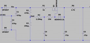
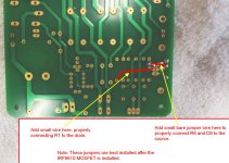
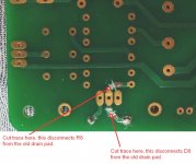
Ian was kind enough to post his fix for the -Vbias mosfet in post #738 and #739
Ian's fixes were probably better than just swapping the Source/Drain on the IRF9610. However, they are a bit more difficult to apply.
So for an alternative fix, here is how I swapped the source/drain connections to the 9610. I had a 2nd set of boards, so I was able to easily show how I did it.
I also used a 1uf cap for C4 that I had on hand and left C5/C6 at .15uf per the BOM.
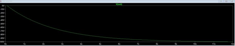
This gave me right at -100v for -Vbias and it takes right around 8-10 seconds to reach that voltage.
gabo
Ian was kind enough to post his fix for the -Vbias mosfet in post #738 and #739
Ian's fixes were probably better than just swapping the Source/Drain on the IRF9610. However, they are a bit more difficult to apply.
So for an alternative fix, here is how I swapped the source/drain connections to the 9610. I had a 2nd set of boards, so I was able to easily show how I did it.
I also used a 1uf cap for C4 that I had on hand and left C5/C6 at .15uf per the BOM.
This gave me right at -100v for -Vbias and it takes right around 8-10 seconds to reach that voltage.
gabo
Attachments
Last edited:
....R43 and R44 have been replaced by resistors 1w 500v the 2w had trouble entering, Ian do you think that the power dissipation level of the 1w is sufficient?
R43 & 44 are dissipating a small fraction of a watt, so your 1w resistors are good.
Caution regarding Mk2 C12
I’m ordering my parts and just realized that those who had already built the Mk2 amplifier PCB with Mk2 power supply (PS) as published by Marc, with Prasi’s GB, will likely have >100Vdc on C12, which, as specified, has a max rating of 100v. gbowling measured -104 v with the specified Toroidy power transformer. This situation is due to the error on the PS PCB gingertube and gbowling discussed above.
If you have not corrected the PS error, you might want to watch the integrity of C12 closely. I’m not sure about the failure mode and I assume several BH EL34 Mk2s have been working without this failure for some time, but personally I would err on the side of caution and not operate it before fixing the PS problem.
Last edited:
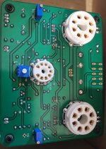
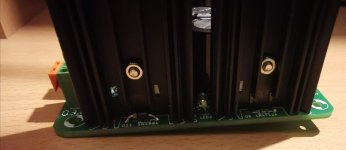
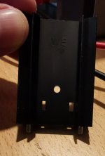
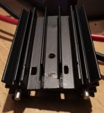
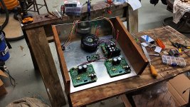
I finally almost finished with the assembly of the power supply, the modification proposed by Ian does this easily. I modified the heatsink so that the diodes pass and that I can screw them.
The capacitors C4 C5 and C6 that I mounted are 0.33uf 250v these are the largest I could find at mouser, the rest I followed Ian's advice
I just have to clean with isopropyl alcohol and try the card, I put you some pictures.
François the C12 capacitor you are talking about is that of the amplification card?
Attachments
Last edited:
François the C12 capacitor you are talking about is that of the amplification card?
Your power supply (PS) board is looking good!
Yes, I’m talking about C12 on the BHEL34 amplifier PCB. Since you have made the correction in the PS I don’t think it is essential that you replace C12 with a higher voltage part, but C10 was specified as 160V, so I will increase my C12 rating as I’m buying my parts now. I have not looked what is available and will fit the board.
Could you post the Mouser part # for those .33/250v capacitors you were able to fit on the PS board, please.
BH Rolls off the production line
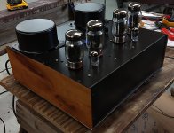
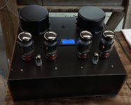
I finally finished up my BH, well at least for now. They are never finished as there are always tweaks to do, but it's going in the music room for listening for a while.
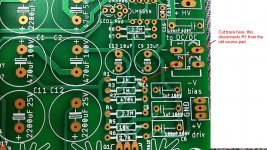
After assembling and testing, I had to make one last modification on the PSU. The -Vbias output with no load was -100v. However, when I connected the channel boards and loaded it, the voltage dropped to around -55v.
That was too low to successfully adjust the bias of my output tubes. With R42/43 adjusted all the way, I could still only get the bias current down to 80ma.
So I adjusted R2 on the PSU board from 470K down to 150K (paralleled a 220K with the existing 470K). This upped the -Vbias to -70v under load and that worked.
Now it's time to have a cold beer in quarantine and listen to some tunes!
gabo
I finally finished up my BH, well at least for now. They are never finished as there are always tweaks to do, but it's going in the music room for listening for a while.
After assembling and testing, I had to make one last modification on the PSU. The -Vbias output with no load was -100v. However, when I connected the channel boards and loaded it, the voltage dropped to around -55v.
That was too low to successfully adjust the bias of my output tubes. With R42/43 adjusted all the way, I could still only get the bias current down to 80ma.
So I adjusted R2 on the PSU board from 470K down to 150K (paralleled a 220K with the existing 470K). This upped the -Vbias to -70v under load and that worked.
Now it's time to have a cold beer in quarantine and listen to some tunes!
gabo
Attachments
Your power supply (PS) board is looking good!
Yes, I’m talking about C12 on the BHEL34 amplifier PCB. Since you have made the correction in the PS I don’t think it is essential that you replace C12 with a higher voltage part, but C10 was specified as 160V, so I will increase my C12 rating as I’m buying my parts now. I have not looked what is available and will fit the board.
Could you post the Mouser part # for those .33/250v capacitors you were able to fit on the PS board, please.
François here is the reference of 0.33uf 250v capacitors from mouser for C4-C5-C6 R66ID3330Z36AK.
Here are also the references for the Molex male and female sockets:
- 22-11-2022 2,54mm 2pin male
- 22-01-3027 2,54mm 2pin Socket (Female)
- 22-29-2031 2,54mm 3pin male
- 22-01-3037 2,54mm 3pin Socket (Female)
- 08-55-0101 contact
I hope it will help you
I finally finished up my BH, well at least for now. They are never finished as there are always tweaks to do, but it's going in the music room for listening for a while.
After assembling and testing, I had to make one last modification on the PSU. The -Vbias output with no load was -100v. However, when I connected the channel boards and loaded it, the voltage dropped to around -55v.
That was too low to successfully adjust the bias of my output tubes. With R42/43 adjusted all the way, I could still only get the bias current down to 80ma.
So I adjusted R2 on the PSU board from 470K down to 150K (paralleled a 220K with the existing 470K). This upped the -Vbias to -70v under load and that worked.
Now it's time to have a cold beer in quarantine and listen to some tunes!
gabo
Hello Gabo,
I don't understand why your supply voltage -Vbias is so low! Normally with the voltage doubler you should be much higher, why t does not replace R1 by 10 ohm and R6 by 100 ohm and R2 by 22k you would have a much higher voltage. I do not know if this bothers for the KT88 but I followed Ian's advice.
Steven
With the original values, R2 470K, R1 1K, R6 2.7K, that's the correct voltage. I already had the boards built and wanted to do minimal changes for now.
I was just surprised when I loaded it up and the voltage went from -100 to -55. But studying the circuit a bit, that looks to be correct. The load presented by the channel board is somewhere around 3k to 3.5K ohms.
It was easy to add a 2nd resistor on top of R2 470K and that got things in a range that I could properly adjust bias for my KT88s. I suppose I could do the same for R1 adn R6 easy enugh. But for now I'll leave it as I have it adjusted and sounding good. I do have another set of boards and intend to build another BH, so I'll make all these changes there.
Thanks, gabo
Now it's time to have a cold beer in quarantine and listen to some tunes!
gabo
Hi gabo,
Amp looks great, well done
")
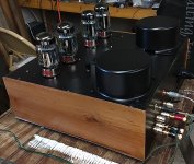
Are those KT-88..? Can you share more pics, please?
Thanks for sharing.
Bekim
.......powering the BHEL34?
Should I use Ian's values for R1, R2 and R6?
My plan is to use Ian’s values. But if you have already bought the resistors, install like gabo did and add a parallel resistor to reduce R2 to somewhere between 150k (gabo’s value that works fine) and 22k (Ian’s value).
What are the best values to use on the PSU when powering the BHEL34?
Should I use Ian's values for R1, R2 and R6?
Many thanks
Karl
The best values are a bit subjective. If you put the circuit in LTSPICE, you can model many scenarios. Having played with it a bit, my 2 cents are as follows.
R1 - This is best below 400 ohms, ripple is a tad lower when that resistor is small and a small value also gives you a few more volts output. Pretty much anything from 10 ohms like Ian has up to around 400 ohms works well. So use what you have and if you've already stuffed the 1k in there you can parallel anything over the top of it to reduce it down.
R2 - You can gain a bit of reduced ripple by making this higher, but that also reduces -Vout. I think anything from Ian's 22K up to about 150K max is good. So again, use what you have and/or parallel something over the top of the 470K is you've already installed it and want an easy fix.
R6 - Lowering this gives you more -Vout. I think the existing 2.7K is too high. Anything from Ian's 100 ohms up to about 1.5K works ok.
From LTSPICE, here are some numbers. These aren't going to be exact due to not being able to model the load accurately. But they will get you in the ballpark.
R1, R2, R6
10, 22K, 100 - Vout = 138v, Current through 9610 = 44ma
10, 150K, 100 - Vout = 123v, I6 = 38ma
500, 150k, 100 - Vout = 122v, I6 = 37
500, 150K, 1.5K - Vout - 87, I6 = 27
After my original post that took R2 down to 150K. I wound up changing a few more things to improve it. Paralleling a 270 ohm across the 1K R1 to get 212 ohms. And a 47K across 470K R2 to get 43K, and a 3.3K across R6 to get 1.5K. Here are the results from that.
212, 43K, 1.5K - Vout = 100v, I6 = 29ma - That's modeled from LTSPICE. The actual measurements were a bit higher, -105V and around 31ma.
It's easy enough to remove the components, but I already had mine assembled in the chassis and didn't want to remove everything and reassemble. I've already done that about 4 times, so getting tired of doing it.
Someone asked for a few more pictures, here you go..
gabo
Attachments
I’m ordering my parts and just realized that those who had already built the Mk2 amplifier PCB with Mk2 power supply (PS) as published by Marc, with Prasi’s GB, will likely have >100Vdc on C12, which, as specified, has a max rating of 100v. gbowling measured -104 v with the specified Toroidy power transformer.
I looked at this again and it appears that the Mosfets (Q5 &Q6) and associated circuitry requires enough current through R39 that the voltage across C12 should remain below the rated 100V. My apologies for sounding a false alarm.
Someone asked for a few more pictures, here you go..
gabo
gabo, what dimensions are the metal part of your enclosure if you don’t mind my asking? It seems a nice size to work with and I’ll need to see if it’ll fit in my rack or whether I’d just need to build a floor stand
Thanks!
gabo, what dimensions are the metal part of your enclosure if you don’t mind my asking? It seems a nice size to work with and I’ll need to see if it’ll fit in my rack or whether I’d just need to build a floor stand
Thanks!
It's 16" wide, 14" front to back, and 4" deep. If I did it again, I would try to make the 14" dimension a bit smaller. I think inside there are places I could have made things a bit closer and took out a couple of inches there.
The problem is, with 14" + the connectors out the back, you actually wind up with needing about 16" front to back.
Also, just for completeness. I also installed a fan on the bottom and some holes on top and back for venting. The fan is a standard PC fan, but with a resistor to slow it down so it's very quiet. I originally put the fan in due to it generating a lot of heat. However, with the PSU fixed and working properly it doesn't seem to be creating as much heat as it did. But it's still a nice idea to keep things cool.
gabo
- Home
- Amplifiers
- Tubes / Valves
- EL34 Baby Huey Amplifier