gabo,
Thanks for sharing you progress and findings. Very helpful and we are enjoying the process as well as gaining insight.
By my calculation R14 (10 Ohm) dissipates around 0.4 watts steady state, so a 2 watt resistor should be fine. The 10k resistor will dissipate a lot more than 5 watts initially, but goes to zero when the switch bypasses it a few seconds later. I might install the PSU board vertically against a chassis side and put 10k between the board and against the chassis for some additional thermal mass and heat sinking.
Good luck with you build.
Good points Francois. The 10ohm probably should be changed to a 2w in the BOM. It's probably not a problem as it has a bit more room and with the low dissipation, won't heat up much.
I was more concerned with the 10K being right up against the NTC. But as you point out, after the timer expires it carries no current, so isn't going to heat up at all. As long as we can give enough space for the NTC, which does heat up, it should be ok. With the angled way I installed the 10K, I gave the NTC some space underneath.
It might actually be a better idea to remote mount the NTC to give it enough space.
I will continue to post as my project progresses, it's also helpful for me to type things out. It forces me to stop and think about things.
gabo
I was more concerned with the 10K being right up against the NTC. But as you point out, after the timer expires it carries no current, so isn't going to heat up at all. As long as we can give enough space for the NTC, which does heat up, it should be ok. With the angled way I installed the 10K, I gave the NTC some space underneath.
It might actually be a better idea to remote mount the NTC to give it enough space.
gabo
Hi gabo,
I believe you worry about the angled 5w resistor (in R17 posistion) on the PS PCB in close proximity to the NTC thermistor. R17 is an alternative to using a choke. I thought I read in an earlier post you were waiting for a choke, so only one resistor is needed, either in position R17, or across the choke connectors, until the choke is installed. Then no R17 is needed.
Re. thermistor, it also dissipates a fraction of a watt in steady state, so not to worry too much. Personally, I will install it underneath the PCB, bent against it, but slightly away for ventilation.
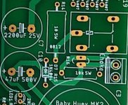
I also don’t see R14 or more likely R15 - I see only one 5w resistor besides the relay. Perhaps I’m not seeing correctly. Where is your 10k R15 installed? It might help if you give us a close-up of your PSU board.
I like your new thread in the Parts forum on connectors and other chassis related items needed for completing a BH build. Perhaps you wish to post the link here for other BH builders to see.
Last edited:
Sorry Guys, .... Marc is down with serious illness, hope he recovers soon and continues with his wonderful contributions and also his diy passion!
I wish him a speedy recovery!
regards
Prasi
Thanks Prasi, and so sorry to hear about Marc’s illness. Please tell him we hope and pray for speedy recovery and good heath.
Oh wow, best wished to Marc!! Sorry to hear and hope he recovers soon.
Francois, no it's not R17 that I'm talking about, it's R15 and the NTC (R16). Here are two pics, one before the components were installed and the other with the components.
Hope that helps.
And thanks for the comments on the chassis thread on the parts forum. I'm building a custom chassis, starting from sheet aluminum that I purchased off ebay. It's almost another project just to do the chassis, but I hope to learn enough and post enough info for others to attempt this as well. Here's a link to the thread. Chassis parts, power entry, switches, terminals, RCA, Speaker, etc.
I'm hoping to learn enough to eventually do a "build guide" just for building a chassis. Something that could be used on any project with a few modifications.
gabo
Attachments

Last edited:
Francois, no it's not R17 that I'm talking about, it's R15 and the NTC (R16). Here are two pics, one before the components were installed and the other with the components.
Hi gabo,
The pics helped a lot. Sorry, I am traveling, so I looked at the last electronic pic of the PCB I saved, rather than the actual PCB, and it turned out to be wrong! R15 is on the PCB where R17 was shown before!
As I stated before, the thermistor, like R15, is not going to dissipate much after the relay turned on, so I’m not going to worry about it. I plan to put the thermistor below board as I had said, but that is more for aesthetic reasons, so that R15 is not angled.
Actually, using a large-bodied R14 against the plastic cover of the relay or the capacitor body on the other side is more of a concern to me. I suggest to install it below the PCB if possible.
Last edited:
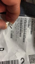
So the connector that was specified in the BOM for the MK2 power supply, the Molex 26-62-4020, which is incorrect and only has one pin per the picture below, can be replaced by Molex 26-60-4023.
That is also the part that is listed for both the high voltage and the 6.3 Vdc connection on the MK2 channel board. For two channel boards and the power supply board, you'll need 5 of those.
Also the 3 pin connector for the bias and driver (on the MK2 power supply it's labelled -V bias and +V driv, and on the channel boards it's labeled Vaux) are different connectors in the respective BOMs. On the MK2 PSU BOM it's specified as Molex 38-00-6293, on the channel boards BOM it's specified as Molex 22-23-2031. Is there a reason these are different? I think they should probably be the same, but maybe there is a reason for them being different.
Then there is the connector for Input and Feedback, which is Molex 22-23-2021.
Does anyone know the correct part numbers for the matching connectors for each of these? I need to make wiring connectors for each of these, but not sure which parts to order to mate up with each. Molex lists quite a few potential mates as the whole series of connectors is quite expansive, but I can't figure out which ones are for these exact headers.
Thanks, gabo
Attachments
Just in case I'm not the only person who doesn't know about molex connectors ") It seems these connectors are standard 2.54 and 3.96mm connectors.
It seems these connectors are standard 2.54 and 3.96mm connectors.
To build up a few for my bench instead of purchasing one at a time, I ordered this kit off amazon.
https://www.amazon.com/gp/product/B01M69TKAM/ref=ppx_yo_dt_b_asin_title_o00_s00?ie=UTF8&psc=1
That's should contain enough to get the 2 and 3 pin 2.54mm connectors built.
For the 3.96mm connectors, I couldn't find a similar kit so I purchased these.
https://www.amazon.com/gp/product/B07SQ52GX7/ref=ppx_yo_dt_b_asin_title_o00_s00?ie=UTF8&psc=1
Should be able to connect three together to get power from the PSU board to both channel boards.
I'm not sure what the exact part numbers off mouser would be.
gabo
It seems these connectors are standard 2.54 and 3.96mm connectors. To build up a few for my bench instead of purchasing one at a time, I ordered this kit off amazon.
https://www.amazon.com/gp/product/B01M69TKAM/ref=ppx_yo_dt_b_asin_title_o00_s00?ie=UTF8&psc=1
That's should contain enough to get the 2 and 3 pin 2.54mm connectors built.
For the 3.96mm connectors, I couldn't find a similar kit so I purchased these.
https://www.amazon.com/gp/product/B07SQ52GX7/ref=ppx_yo_dt_b_asin_title_o00_s00?ie=UTF8&psc=1
Should be able to connect three together to get power from the PSU board to both channel boards.
I'm not sure what the exact part numbers off mouser would be.
gabo
Unfortunately the group buy is over, but if you post a request on the GB thread, Prasi, who organized the GB, might consider another round.
See: GB for Baby Huey PCB
See: GB for Baby Huey PCB
Last edited:
Mk2 Channel Board
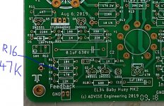
Just a heads up MK2 builders. For the MK2 channel boards, the silk screening for R16 shows it to be 15K.
This was changed with the latest updates to 47K, which is what it is listed as in the BOM. Just don't forget to install the correct one. I have attached a picture of the board with notation.
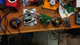
Also a pic of my first finished and testing channel board. Very much a science project at this point
But the channel tested out nicely. With a 40ma bias point, I get around 32 watts output and all looks clean.
One tip, I tested my board without the power tubes installed, to make sure all was ok and to balance out V1 and V2. Which was no problem, mine balanced out around 186v.
However, make sure you have R41 and R42, your bias adjustments, set all the way clockwise prior to powering up with the power tubes. I didn't do that, plugged in the power tubes and powered things on. When I tested the bias, it was at almost 3 volts on each tube!! Way too high, and it takes many turns of R41 and R42 to get it down in range. By the time I got both of them dialed down, the tubes had heated up quite a bit.
To avoid that, just make sure you have R41 and R42 adjusted for minimum bias prior to powering up with power tubes. I should have powered mine off quickly to do a pre-adjustment prior to powering back up with the Kt88s.
gabo
Just a heads up MK2 builders. For the MK2 channel boards, the silk screening for R16 shows it to be 15K.
This was changed with the latest updates to 47K, which is what it is listed as in the BOM. Just don't forget to install the correct one. I have attached a picture of the board with notation.
Also a pic of my first finished and testing channel board. Very much a science project at this point
But the channel tested out nicely. With a 40ma bias point, I get around 32 watts output and all looks clean.
One tip, I tested my board without the power tubes installed, to make sure all was ok and to balance out V1 and V2. Which was no problem, mine balanced out around 186v.
However, make sure you have R41 and R42, your bias adjustments, set all the way clockwise prior to powering up with the power tubes. I didn't do that, plugged in the power tubes and powered things on. When I tested the bias, it was at almost 3 volts on each tube!! Way too high, and it takes many turns of R41 and R42 to get it down in range. By the time I got both of them dialed down, the tubes had heated up quite a bit.
To avoid that, just make sure you have R41 and R42 adjusted for minimum bias prior to powering up with power tubes. I should have powered mine off quickly to do a pre-adjustment prior to powering back up with the Kt88s.
gabo
Attachments
MK2 Schema with Voltages
When I do a project like this, I like to keep a schema with voltages on it. That way if something happens in the future, I have a lot of info for troubleshooting.
So I took Marc's MK2 channel schema and added measured voltages from one of my channel boards.
These voltages are with the power tubes removed, but output transformer and 12ax7 installed and adjusted.
I thought someone else might find it useful, so I am posting it up here.
gabo
Attachments
Last edited:
MK2 Chassis
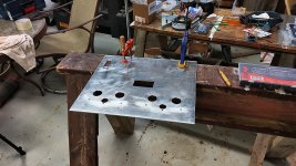
Now that I've finished my MK2 power supply and channel boards. I'm turning my attention towards my chassis.
I started with a sheet of 1/8" aluminum, cut to 16" x 14" and now laying out the holes and cutting and drilling them.
This will be the top of the chassis.
gabo
Now that I've finished my MK2 power supply and channel boards. I'm turning my attention towards my chassis.
I started with a sheet of 1/8" aluminum, cut to 16" x 14" and now laying out the holes and cutting and drilling them.
This will be the top of the chassis.
gabo
Attachments
Hello all,
Another Baby Huey group buy for PCBs for BHEL34, BHEL84 and PSU PCBs is likely to begin in the GB thread as mentioned in below thread.
If anyone here wants to participate or stock up on the PCBs, please post your requirements in the GB thread. GB will go live if I receive requirements for at least 50PCBs each .
Group Buy Thread: GB for Baby Huey PCB
I also received a comment/ suggestion from a gentleman that BHEL34 can also use 6V6 tubes. I am no expert on tubes , so if someone is willing , they could post a detailed write up on how to do it manually on the existing BHEL34 PCBs.
regards
prasi
PS as usual, PCBs will be 2.4mm thick, 70 um copper , ENIG-gold , green mask and white silk.
- Home
- Amplifiers
- Tubes / Valves
- EL34 Baby Huey Amplifier