Got the first board built and connected, but I can't set the bias on the tubes. It comes on with B+ of 430v off the 270v winding (my mains voltage runs at close on 250v most of the time) which starts to drop as the tubes warm up and the bias starts to climb... and keeps on going up, until I bottle it and pull the plug at somewhere around 80ma (0.8v on a 2V meter setting) with the pots set around the mid-point - I start to get a increasingly loud buzz from the speaker at the same time. I have been over the board, no dry joints or shorts, the only thing I could find was that soldered D5 in the wrong way round - I have corrected that but it still does the same thing. Any clues where to start looking?
The first thing to do is to remove the tubes. Check your HV and +- bias voltages to make sure all is ok. Next you want to check the bias voltage adjustment range. Meter on DC volts and - lead on ground. Check the voltage on each el34 control grid. You should be able to adjust it to a high enough negative value to reduce current to the desired amount. With 400+ volts you will need at least -45 volts. Run the bias pots through their entire range to make sure you have a good smooth voltage adjustment. Then return them to the maximum - voltage position.
Keep in mind that the pots work backwards. The left one adjusts the right tube/test point and visa versa.. That confused me the first time I tried to bias the outputs.
If the bias voltage is not adjusting or won’t go to at least - 40 then there may be an issue with the circuitry. If you have say, -50v max. then set the pots to max. voltage, power down, then plug in the 12ax7 and adjust the balance pot for equal plate voltages on each side of the tube. After that is setup input a signal and check for equal ac drive voltages at the output tube grids ( as well as the -50v dc)
Power down, install the output tubes and you should have a low plate current which you can then adjust up to your desired amount. Those opposite bias pots take some getting used to and perhaps that was what was causing your adjustment problems to begin with. Anyway, good luck getting it running.
Thanks, that was helpful, I was able to get around 60ma on the tubes (KT888's so well within the limits) with that and dropping R39 down to 7.5k. Although I think I may have fried something by firing it up with D5 reversed, I only get 20v across one side of the 12AX7 and nothing across the other side and no adjustment, plus no adjustment to the bias on one of the output tubes. I will build up the second board a bit more carefully, and see how it goes.
Marc,
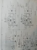
I decide on regulated HV because my input ac ranges from 210 to 240V I refer to your TENA power supply schematic in post 299.
1) what is voltage rating for C17 and C19 for the HV power supply ? Can I use 10Uf or higher instead of the 1UF ?
2) What is the wattage rating for the 1N4742A?
3) Can i use IRF 740 in place of IRF 840 ? My input supply is about dc 430V
Thank you
Regards
kp93300
Last edited:


Happy holiday Marc. Thanks for the reply.
Can anybody advise what the appropriate value for R 17 and R18 trimmer value.
Can i use 50 to 100k?
0.5 W rating ok?
R17/18 form a voltage divider with the 1 meg resistor to ground. The value of R17/18 depends on the amount of adjustment you need. If you have 430volts going into the drain of the mosfet and r17/18 is 100k you will be able to adjust as low as about 395v and 250k would allow you to go to about 345v. .5 watt rating is ok.
Keep in mind that the circuit shown is not a voltage regulator but a long time constant filter. The zener does not need to be high power. It is there to protect the gate from over voltage. Just make sure you get the polarity correct.
Last edited:
Mosfet substitute.
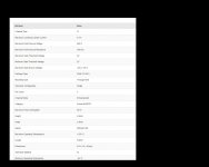
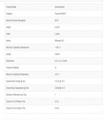
I bought STMICROELECTRONICS
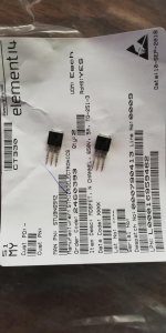
STU9N65M2 and noticed that the pins are rusty .
Can I substitute with STU9N60M2 N-Channel MOSFET, 5.5 A, 650 V MDmesh M2, 3-Pin IPAK STMicroelectronics ?
I bought STMICROELECTRONICS
STU9N65M2 and noticed that the pins are rusty .
Can I substitute with STU9N60M2 N-Channel MOSFET, 5.5 A, 650 V MDmesh M2, 3-Pin IPAK STMicroelectronics ?
Attachments
Last edited:
Hello kp93300,
I am back from holidays in Mauritius Island and ready to answer to your question
I am surprised that you received STU9N65M2 that have the pins rusty I got mine from Mouser : https://www.mouser.fr/ProductDetail/STMicroelectronics/STU9HN65M2?qs=k5OWtXsTJao6DGFY%2bWbTvw== without any problem May be you can use some de-oxide liquid to clean them ?
For R17 & R18 : 50 or 100 k will be perfect as Bfpca suggested... You can also use a fixed resistor ! I will make a PCB sometime...
Hi carlthess40,
The EL34 and the EL84 Baby Huey are using EXACTLY the same schema, only the output tubes socket and some resistors values are different, that is for this reason that I published only one BOM with the indication of the different components in green for the EL84 version
I add it again to this post. I have not published a purchase list from Mouser, only suggested some part references.
Best regards to all,
Marc
I am back from holidays in Mauritius Island and ready to answer to your question
I am surprised that you received STU9N65M2 that have the pins rusty
I got mine from Mouser : https://www.mouser.fr/ProductDetail/STMicroelectronics/STU9HN65M2?qs=k5OWtXsTJao6DGFY%2bWbTvw== without any problem May be you can use some de-oxide liquid to clean them ?For R17 & R18 : 50 or 100 k will be perfect as Bfpca suggested... You can also use a fixed resistor ! I will make a PCB sometime...
Hi carlthess40,
The EL34 and the EL84 Baby Huey are using EXACTLY the same schema, only the output tubes socket and some resistors values are different, that is for this reason that I published only one BOM with the indication of the different components in green for the EL84 version
I add it again to this post. I have not published a purchase list from Mouser, only suggested some part references.
Best regards to all,
Marc
Attachments
You have the link to Mouser in my previous message, post 333, about 2500 pieces in stock for less than 1 € each
They look very close, this is yours : https://www.mouser.fr/datasheet/2/389/std9n65m2-955725.pdf
but I would ask your supplier why they shipped rusty parts ? Personally I would not buy from Farnell (element14) when I can get part from Mouser or Digikeys !
Rgds
Marc
They look very close, this is yours : https://www.mouser.fr/datasheet/2/389/std9n65m2-955725.pdf
but I would ask your supplier why they shipped rusty parts ? Personally I would not buy from Farnell (element14) when I can get part from Mouser or Digikeys !
Rgds
Marc
Hi guys
I have 6 of the tube sockets that I ordered before I realized that I had the EL 86 boards and it takes different tube sockets
these are for the EL 34 and they are ceramic with gold pens PCB mount
I just want 8 dollars for all of them and shipping
I’m in Florida so best to ship in the us
Send me a email carlthess@yahoo.com
I am (still) warming up to build myself a Baby Huey using Prasi's boards. I wonder if anyone has done monoblocks of this and can comment on the relative merit vs an integrated? Also,
If going the monoblock route, i suppose a simple passive preamp should be good enough to drive the amp, right?
If going the monoblock route, i suppose a simple passive preamp should be good enough to drive the amp, right?
- Home
- Amplifiers
- Tubes / Valves
- EL34 Baby Huey Amplifier