Thanks Dak808, i will be testing the voltages this weekend and double check what they are!
Agreed it could be grief, there are a few UK companies that can make me a transformer if it doesn't suit my needs. I will keep you posted!
Hi vishalk, I guess they will be too high by 10% or so.
Pointless replacing the transformer at this stage (unless money is no object) the ''Bucking'' transformer is a perfectly normal fix in the UK for using 220 volt kit on 240/245 volt mains. (See the link Bucking Xfmrs on post #17.)
Alan
Last edited:
Bucking Transformer
Bucking Transformer DIY (Drop 240V to 220V) | Sound Kontrol (DASK)
Alan could i just buy a toridial transformer? 240v to 20/24V? What VA rating would be ideal? Want to be able to place it in the chassis if possible.
Thanks
Bucking Transformer DIY (Drop 240V to 220V) | Sound Kontrol (DASK)
Alan could i just buy a toridial transformer? 240v to 20/24V? What VA rating would be ideal? Want to be able to place it in the chassis if possible.
Thanks
Yes, a 50VA 20 or 24 volt toroidal will be fine.
Do it this way:
Work out the current the amp will draw when working at 220 volts. Rough is fine as long as we over calculate the need. Heaters need 46 Watts, the HT (B+) needs 85 or 95 Watts (assumes the KT88s need 40 to 45 each and the 6N8ps need 2.5 watts each). Total is roughly 141, so call it 150W. That is about 0.7 Amps at 220 volts.
The bucking transformer secondary has to carry a minimum of 0.7 amps, so using the two times factor for losses and cool running = 1.4 Amps minimum. That is 34VA minimum for a 24 volt transformer. Therefore, best go to 2 Amps and 50VA.
I would build the amplifier first, and power it from the Bucking transformer externally like your example. Best to know the native level of hum it has, before adding more magnetic loops in there with so much iron... I expect there will be room in there anyway.
Alan
TTS50/Z230/24V Transformer toroidal 50VA 230VAC 24V 2.08A 0.7kg O78mm 7429504790737 | eBay
Thanks Alan i ordered one of these!
Thanks Alan i ordered one of these!
Alan that's a better idea! Thanks mate I will use this
My point is why should go out of your way to make the amp work when the proper provided PT would do the exact same thing? You should hold the seller to provide you with the proper PT. Unless you bought the kit second hand or used. In this case then you have to make do.
I hope you know you are working with lethal voltages? Not really smart if you have no experience with electronics. Wiring from the schematic should be self-evident, otherwise it may be necessary to ask someone with experience. Not being mean, just trying to get the point across this thing can kill you.
My point is why should go out of your way to make the amp work when the proper provided PT would do the exact same thing? You should hold the seller to provide you with the proper PT. Unless you bought the kit second hand or used. In this case then you have to make do.
The problem is the kit is bought from china and it comes with 220v transformer, there is not much i can do, just got to work with what we have! It's a new kit and thats what they provide.
Thanks VT52 for your concern and my safety, but not to worry i've worked on many valve amplifiers, just never built one from scratch! I will of course be very safe!
Cool! We need more members, not fewer
")

vishalk,
The KT88 tube does not have any connection to pin 1.
The EL34 Does have a connection to pin 1, it is the Suppressor Grid of the EL34 True Pentode. It must be connected to something.
Was this amp specified for using both the KT88 tube, and also for using the EL34 tube?
The KT88 has different maximum ratings for plate voltage, plate dissipation, screen voltage, screen dissipation, and cathode current; versus the maximum ratings of the EL34. Do not use the EL34 in place of the KT88 unless you check all these parameters. Otherwise there could be damage to the tube, and depending on the circuit and parts, could be a problem for other parts (i.e. less current draw causing B+ volts to go too high for the B+ capacitors) Check before trying.
Last edited:
..The KT88 tube does not have any connection to pin 1....
It should be the metal (base) shell.
(I note the JJ 2006 data says different.)
It would normally be tied to ground.
If tied to cathode as shown, there is a small slight shock hazard. (But it is unwise to put your hands close to a large hot bottle: I once had a hand-burn in the shape of a 6550.) There is the unlikely risk of some metallic object loose on the chassis shorting-out the cathode bias, which would be bad.
The indicated connection 8-1 probably won't cause any trouble.
The shell "should" be grounded for maximum safety and shielding. I do not think this is very important in home audio. I am distressed that a major maker shows KT88 p1 as "G3" (though picture shows G3 to K).
I'd just leave pin 1 floating.
Which is indeed the only thing you can do with the short-count socket they shipped.
PRR,
Good catch. Pin 1 is the shield. And I could never understand the need for a shield at (only) the base of a Beam Power tube. Also, the JJ that says it is G3, just seems like a reminder of about the only Power Pentode tubes that have G3 on pin1 is the 6CA7/EL34. Curious.
Good catch. Pin 1 is the shield. And I could never understand the need for a shield at (only) the base of a Beam Power tube. Also, the JJ that says it is G3, just seems like a reminder of about the only Power Pentode tubes that have G3 on pin1 is the 6CA7/EL34. Curious.
Last edited:
The problem is; the more people support these companies that do not provide the correct product or are just unloading excess inventory because of some government bureaucrat's orders under "advisement" from the party, the more they will continue to do so. Meanwhile, a small company in your country that can make the same thing for you but at a realistic price (not a government supported price) can not compete and will fail or will not prosper. In the end it all comes down to the consumer's choice.The problem is the kit is bought from china and it comes with 220v transformer, there is not much i can do, just got to work with what we have! It's a new kit and thats what they provide.
Today, that first post link says 110 - 120, 220 - 240.
230V +/- 4.3% = 220 - 240V
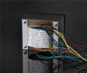
If you look at the pics shown in the first post the PT only has 2 110vac inputs. So there is only 220v or 110 vac input voltage.
However the ebay ad shows 110,120, 220,240 vac input.
Thus there is a discrepancy that could be disputed. These issues should be challenged to ebay and any other outlet that sells this type of equipment.
- Status
- This old topic is closed. If you want to reopen this topic, contact a moderator using the "Report Post" button.
- Home
- Amplifiers
- Tubes / Valves
- KT88 Valve Tube Amplifier Single-ended Amp DIY KIT from China. No instructions!