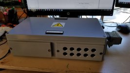
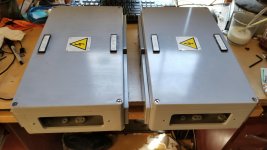
What started off as a "simple" push-pull 807 build has exploded into a less-than-simple idea. First was the massive power transformer, and then a buddy of mine gave me some industrial wiring boxes that I will use for chassis (see attached photos). I'm going for a sort of industrial/transmitter look, so I think they'll work out okay. I'm not afraid of a little machining.
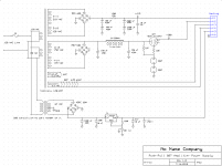
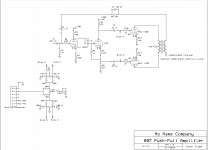
I won't be able to fit an entire amplifier in one chassis, and I only have one power transformer, so I'm thinking of using an external power supply. Attached are the schematics for both the amplifier and its over-complicated power supply.
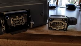
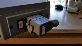
These boxes came with some Harting connectors on them (see photos, not exactly sure what they are). I'm thinking of using them to connect the PSU and amplifier sections. Let me know if this seems unwise.
Also visible in my schematic is the bias circuit. It uses a voltage control on the power supply (using an LM337). Each channel has a balance control, and then there is a third control to balance the two channels. I thought it might be interesting to try, though it's seeming a bit complicated.
The screen grid and preamp/phase inverter stages all share a common 300V regulated power supply, using a 6N7 as a sort of PAS element. I'd like to find a tube with a top cap to take it's place (aesthetic reasons).
I calculated that I'd have a maximum of about 90 mA on that rail. The 807 datasheet specifies a maximum screen current of 16 mA under load. What I'm not sure about is how realistic it is to see this much current on the screen. At 300V, I think that would probably exceed the 3.5W screen dissipation rating of the 807.
I'd love to get some feedback on this slightly impractical design.
I won't be able to fit an entire amplifier in one chassis, and I only have one power transformer, so I'm thinking of using an external power supply. Attached are the schematics for both the amplifier and its over-complicated power supply.
These boxes came with some Harting connectors on them (see photos, not exactly sure what they are). I'm thinking of using them to connect the PSU and amplifier sections. Let me know if this seems unwise.
Also visible in my schematic is the bias circuit. It uses a voltage control on the power supply (using an LM337). Each channel has a balance control, and then there is a third control to balance the two channels. I thought it might be interesting to try, though it's seeming a bit complicated.
The screen grid and preamp/phase inverter stages all share a common 300V regulated power supply, using a 6N7 as a sort of PAS element. I'd like to find a tube with a top cap to take it's place (aesthetic reasons).
I calculated that I'd have a maximum of about 90 mA on that rail. The 807 datasheet specifies a maximum screen current of 16 mA under load. What I'm not sure about is how realistic it is to see this much current on the screen. At 300V, I think that would probably exceed the 3.5W screen dissipation rating of the 807.
I'd love to get some feedback on this slightly impractical design.
Attachments
Last edited:
Your design looks fine to me. Some tube regulator circuits can be noisy. I would be tempted to use 6x 0A2 instead (two in series each). At start up the low resistor value required may over current the 0A2 for around 8-10 seconds until the 807s draw screen current, but I have never damaged a regulator tube that way.
BTW- use low noise diodes on the 415 volt rail.
BTW- use low noise diodes on the 415 volt rail.
Last edited:
Your schematics have some errors. No grid leak resistors back to bias points, and possibly too long an RC time constant for the bias voltages (possible hot start stress on 807's). Screen supply bridge rectifier wiring. 6N7 heater not connected to cathode. Main heater not connected to ground somehow. Is that 42VAC winding actually 21-0-21 ?.
OA2 can cope with a low level of bypass cap (eg. 0.047uF), and upper valve can have a resistor across it to help startup of the lower valve.
OA2 can cope with a low level of bypass cap (eg. 0.047uF), and upper valve can have a resistor across it to help startup of the lower valve.
Your schematics have some errors. Possibly too long an RC time constant for the bias voltages (possible hot start stress on 807's). Screen supply bridge rectifier wiring. 6N7 heater not connected to cathode. Main heater not connected to ground somehow. Is that 42VAC winding actually 21-0-21 ?.
OA2 can cope with a low level of bypass cap (eg. 0.047uF), and upper valve can have a resistor across it to help startup of the lower valve.
Didn't notice that bridge rectifier wiring error. That probably wouldn't work too well.
Why would the 6N7 heater be connected to the cathode? Other heaters are not grounded through a virtual center tap simply because I didn't want to draw it into the schematic. I do believe that the toroid is a pair of 20 or 21 volt windings. That centertap is not necessarily supposed to be grounded. Drawing error.
Didn't even think about the RC time constant for the bias supply, that's definitely worth looking at more carefully.
Also, think I'll need that choke on the 300V line with that regulator in place?
No grid leak resistors back to bias points,
Could you please clarify on exactly what you mean by that? I assume this is on the power tubes.
Thanks for the suggestions.
Highly recommended not to float heaters. 6N7 datasheets don't typically show heater-cathode voltage limit, but a German datasheet shows a 45V limit.
42Vrms full-wave rectified could expose LM337 to too high a differential voltage.
Power tube grid leak is the resistance between the grid terminal and the grid bias voltage (the closest bypassed circuit node) - the schematic shows no such resistor.
Choke with regulator - depends on what level of mains frequency ripple you want to get down to in the output stage, and whether the regulator and NFB can do that sufficiently - I'd suggest you suck it and see what hum residual is in your output signal after you've tracked down all other hum contributors.
Last edited:
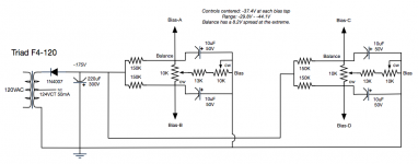
You have the right idea in your bias/balance circuit, but you can achieve the same thing I believe with a simpler circuit. (see attachment, but ignore the voltages and resistor/pot sizes and just look at the topology).
Also since this is a push pull amp, the bias supply doesn't need to be of the highest integrity. You can get rid of the three terminal regulator all together and instead add a small filtering/dropping resistor between the two 100 uF caps, say 1KΩ, or so. Then just feed that raw filtered bias voltage straight into the bias/balance circuit.
Also in your high voltage supply, the caps that are wired in series need voltage equalizing resistors across each cap. Exact value is not that critical as long as they are at least say 100KΩ so you don't draw too much unnecessary current through them.
Attachments
I have no doubt I could do a simpler bias circuit, but I was interested in trying the topology I came up with.
I was under the impression that if a regulated screen grid supply is used, then it's best to have a regulated bias supply so it doesn't change relative to the screen grid when the line voltage changes.
BTW, is there a better tube for a PAS element than the 6N7? I think I have some stray 6L6GCs around, but it seems a bit overkill for this. It'd be cool to use something with a top cap just to keep with the aesthetic of this thing.
BTW, is there any reason I'd want to use an 0D3 instead of an 0A2? I'd use a bunch of zener diodes, but they don't glow purple.
The NFB returns via resistor to input with no input resistor only a series cap. This (with typical modern low-Z sources) will give a rising response over much of the audio band. Rising from LF to 300Hz, flat with no NFB above that. Most such plans return to first tube cathode. Your values seem appropriate for that.
The grid-leak path does go through. However as drawn it puts 100uFd on each driver output, which won't pass over 2Hz. (Which makes the NFB induced rise moot.)
And I agree: over-complicated. FOUR bias trimmers?? Some of which can go to zero bias? Good luck.
The grid-leak path does go through. However as drawn it puts 100uFd on each driver output, which won't pass over 2Hz. (Which makes the NFB induced rise moot.)
And I agree: over-complicated. FOUR bias trimmers?? Some of which can go to zero bias? Good luck.
Attachments
The NFB returns via resistor to input with no input resistor only a series cap. This (with typical modern low-Z sources) will give a rising response over much of the audio band. Rising from LF to 300Hz, flat with no NFB above that. Most such plans return to first tube cathode. Your values seem appropriate for that.
The grid-leak path does go through. However as drawn it puts 100uFd on each driver output, which won't pass over 2Hz. (Which makes the NFB induced rise moot.)
So is there anything you would suggest changing then in terms of the grid leak/100uF capacitors then? I was planning to use 100K grid leak resistors.
I could probably make the circuit a little simpler, but I'm not sure a traditional bias/balance circuit would be much simpler.
Move the 100uF on each 807 grid to other end of the 100k - then you have a grid leak that is 100k back to adjustable bias supply, but also in parallel with some unknown pot. Remove that pot, then you have 100k grid leak, but the bias supply node is high impedance as it is 100k back to power supply and parallel with about 150k to ground. Aim for 100k grid leak to a relatively stiff decoupled power supply voltage - as per datasheet for 807.
Revert to a commonly used bias adjust circuit is the recommendation, until you have enough awareness of what a good bias supply needs to do.
Revert to a commonly used bias adjust circuit is the recommendation, until you have enough awareness of what a good bias supply needs to do.
I have no doubt I could do a simpler bias circuit, but I was interested in trying the topology I came up with.
Okay...nothing wrong with experimenting...
I was under the impression that if a regulated screen grid supply is used, then it's best to have a regulated bias supply so it doesn't change relative to the screen grid when the line voltage changes.
You're getting some amount of "regulation" already by virtue of using a separate winding on the power transformer for screen voltage derivation. I'm not sure how much additional benefit you're really going to see with active regulated screens in this scenario--probably some benefit but not sure if it will be worth the extra effort. On the other hand, if you were to derive the screen voltage from the HV supply itself, it would make more sense to regulate screens.
In the same way, if you were to derive the bias voltage from a tap on the HV winding, it would make more sense to regulate bias. But you have a separate transformer for bias voltage derivation. So the pull down on the HV supply from the output stage delivering higher power output will not really pull down the bias voltage. About all you'll see there is when your A/C kicks on and revs up, but that is short lived.
If you want the highest level of top shelf performance then you would want to regulate plate, screen, and bias.
A 6L6 or another 807 wired in triode mode would work for this purpose. I've also used a 6V6 in this capacity.BTW, is there a better tube for a PAS element than the 6N7?
Yeah, as I got to thinking about it there's no reason for balance pot between the two channels.
Historically I've just copied the bias supply from an amp using similar tubes, although I admit that I've never thought much of it beyond being an adjustable negative voltage supply.
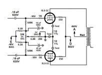
This is the bias supply from the amp I'm currently working on, which seems a little more typical.
Historically I've just copied the bias supply from an amp using similar tubes, although I admit that I've never thought much of it beyond being an adjustable negative voltage supply.
This is the bias supply from the amp I'm currently working on, which seems a little more typical.
Attachments
That is definitely a good thing, I had two pots go open on my Heathkit amp. After the second one failed I just replaced all of them.
If I use this type of bias supply, I still might regulate it, though I might try to use a tube regulator. Maybe an 0A2 or 0D3, plus a 10v zener.
If I use this type of bias supply, I still might regulate it, though I might try to use a tube regulator. Maybe an 0A2 or 0D3, plus a 10v zener.
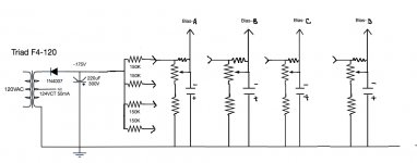
You are still using FOUR trim pots. You might as well just use FOUR separate supplies after the rectifier, and individually trim for each 807 power tube. To me it's less confusing than try to fiddle with the "balance".
And yes, use a 100K grid leak resistor for each tube.
And yes, use a 100K grid leak resistor for each tube.
Attachments
I don't mind the balance system, but my initial idea with 3 balance controls and a single voltage control would have been a pain to use.
I use the balance pot method for PP amps and the single pot per tube method on my SE amps. The balance pot method is a little more effort since it requires more readjustment, whereas the single pot is just adjust to the voltage you want. But, both ways are valid.
- Status
- This old topic is closed. If you want to reopen this topic, contact a moderator using the "Report Post" button.
- Home
- Amplifiers
- Tubes / Valves
- An Excessively Complicated External Power Supply and Bias Circuit for 807 Amp