ThanksWavebourn has half the anser, but he is missing the point that distortion in the tube degrades at a more or less constant rate as bias is increased. There is no "too high to bias his tube properly" threshold; it's a smooth gradient from less distortion to more distortion. When you increase LED current you reduce it's internal resistance, yes, but the increase in LED voltage also causes the tube's internal cathode resistance to increase even more. So overall it's a false economy. Caveat emptor. (<-- me trying to explain to Wavebourn
)
More mentions here:
LED tube biasing, pros and cons
LED bias for 6N1P driver
LED bias for 6N1P driver
LED bias for 6N1P driver
Thanks
Relying on a voltage drop caused by weak tube bias current is not good for repeatability, plus it depends not only on the current, but also on the temperature.
Selecting proper LED for needed bias voltage, plus gyrator anode load that keeps anode voltage stable, guarantees minimal distortions per output voltage swing when tubes age, changed, or bias voltage drifts due to temperature change.
Please see the attached math derivation for dynamic resistance of a diode. Merlin is correct.Better read this and try to understand the difference between "inversely proportional" and "exponential".
(And I referred to this same result in my post #148 in this thread. Note that Rd is in ohms, Id is in milliamps.)
-Gnobuddy
Please see the attached math derivation for dynamic resistance of a diode. Merlin is correct.
(And I referred to this same result in my post #148 in this thread. Note that Rd is in ohms, Id is in milliamps.)
OMG... Is it a some kind of a psychological experiment?
Merlin is correct that dynamic resistance with increase of the current decreases, but he is wrong in his conclusions that it leads to higher distortions.
Gentlemen, would you be so kind to read everything carefully before jumping to conclusions?
Wavebourn, would you be so kind to do real measurements before jumping to conclusions?
Thank you!
I did that since 1970'Th. And also learned to interpret properly results of experiments, and got my diploma successfully, working on projects for Tomsk Institute of Semiconductor Devices.
In the thread where you described your experiment people already explained to you why you got your results. Dynamic resistance has nothing to do with them, voltage bias of the tube does.
We are talking here about LED bias, not about your particular experiment with a tube in sub-optimal regime.
Yes, you are exactly right, bias has more effect on distortion than LED dynamic resistance does. Therefore there is no advantage in boosting LED current, because all it achieves is to increase the bias and thus make distortion worse. You have just confirmed my point.In the thread where you described your experiment people already explained to you why you got your results. Dynamic resistance has nothing to do with them, voltage bias of the tube does.
Last edited:
Oh, reading carefully wasn't the issue. Please take a look at the attached screenshot of your previous post.Gentlemen, would you be so kind to read everything carefully before jumping to conclusions?
As you can see, you quoted Merlin's statement "Dynamic resistance in LEDs is approximately inversely proportional to current" - and you responded "Better read this and try to understand the difference between "inversely proportional" and "exponential".
Now, I don't know what you intended to say, but as a native English speaker myself, there is no doubt that what you actually did say is that Merlin was wrong to use the words "inversely proportional", and that this error came from his lack of understanding of the difference between "inversely proportional" and "exponential".
As I showed in the math derivation in my previous post, "exponential" does indeed lead to "inversely proportional" in this particular case (dynamic resistance of a device with an exponential I-V characteristic.)
Obviously Merlin is well aware of this particular mathematical result, and I would be very surprised if you aren't as well. It's nothing new to anyone who's studied a little semiconductor physics.
As for the rest of whatever long-standing hair-pulling contest this is, I want no part of it. It's all yours, gentlemen! Enjoy your fight, I'm off to do something more fun.
-Gnobuddy
Yes, you are exactly right, bias has more effect on distortion than LED dynamic resistance does. Therefore there is no advantage in boosting LED current, because all it achieves is to increase the bias and thus make distortion worse. You have just confirmed my point.
No, I confirmed my point, that you should select LED material for the particular tube and it's desired regime. Also, I confirmed my point that gyrator anode load rectifies problems caused by temperature dependence of voltage drop on the LED.
Please calm down , you have both a point. Merlin showed that in his circuit distorsion increases when the LED is conducting more, That is an effect that the tube in question might be a little "hot" driven from the beginning. Starting with another tube ( or LED) where the tube is less loaded might give other results. BTW, the difference was not that big.
Both of you make very good contributions here, plese take a step back and go on.
Both of you make very good contributions here, plese take a step back and go on.
It looks like some levity is needed at this contentious point.Please see the attached math derivation for dynamic resistance of a diode. Merlin is correct.
(And I referred to this same result in my post #148 in this thread. Note that Rd is in ohms, Id is in milliamps.)
-Gnobuddy
Ok , when you guys start to bust out the calculus equations it shoots me back to Catholic High School with Brother Pleiman who was almost as deaf as a door knob. But a brilliant teacher. So, in advance math classes he would write out the equations on the black board that needed to be solved. Of course this took some time, and a class of 20, knowing he is stone deaf, would take that opportunity to chat away like a bunch of girls at recess. If he suspected, or maybe it was peremptory strike, you of talking behind his back, he would take one of his chalkboard erasers, the kind made of felt, about 5 inches by 2 inches, maybe 8 ounces, and give you a bean ball right off the noggin. He might have been deaf but his aim was true. With an arm like that, i figure he could have been a minor league prospect, if not for God.
Another side effect for chancing one of his bean balls was that everyone became quite adept at "hitting the dirt" since if you were good at dodge ball and avoided the missile, there could be "collateral damage" to nearby students. So his class was also good practice for air raid drills or duck and cover.
Cheers,
808
Last edited:
It looks like some levity is needed at this contentious point.
Ok , when you guys start to bust out the calculus equations it shoots me back to Catholic High School with Brother Pleiman who was almost as deaf as a door knob. But a brilliant teacher. So, in advance math classes he would write out the equations on the black board that needed to be solved. Of course this took some time, and a class of 20, knowing he is stone deaf, would take that opportunity to chat away like a bunch of girls at recess. If he suspected, or maybe it was peremptory strike, you of talking behind his back, he would take one of his chalkboard erasers, the kind made of felt, about 5 inches by 2 inches, maybe 8 ounces, and give you a bean ball right off the noggin. He might have been deaf but his aim was true. With an arm like that, i figure he could have been a minor league prospect, if not for God.
Actually, it is all quite simple.
When tube works, it's current changes with the signal. It causes change of voltage drop on the biasing LED. When current is lower, change of voltage drop on the LED caused by the signal is less linear than when it is biased by an external current source, so adding an external stable bias current to a variable weak current supplied by the tube, we decrease distortions added by the LED itself, moving it's working point further from sharper curve part.
It can also mean"Inversely proportional" means 1/x. Period.
y = K/x
or if you prefer,
y = K * 1/x
It can also mean
y = K/x
or if you prefer,
y = K * 1/x
Sure. It is not not an exponential function. That's the point. If it was inversely proportional, there would be no such difference.
Edit: But even then, y=K * 1/x would result in higher distortions than y= r0 + k1* 1/(x+k2), where k2 is an external bias.
PS: my daughter has a great graphing tool that she uses for math in the college; when she comes from work I will ask her to use it, to demonstrate different results on graphs.
If what was inversely proportional? What would be different? What's that equation supposed to mean? External bias of what? What are you talking about? Can anyone here interpret what Wavebourn is trying to saySure. It is not not an exponential function. That's the point. If it was inversely proportional, there would be no such difference.
Edit: But even then, y=K * 1/x would result in higher distortions than y= r0 + k1* 1/(x+k2), where k2 is an external bias.
I guess I'd better stop feeding the troll. Wavebourn can shake his fist at the sky all he likes, but it doesn't change reality. Anyone can do the measurements for themselves.
Last edited:
If what was inversely proportional? What would be different? What's that equation supposed to mean? External bias of what? What are you talking about? Can anyone here interpret what Wavebourn is trying to say
I guess I'd better stop feeding the troll. Wavebourn can shake his fist at the sky all he likes, but it doesn't change reality. Anyone can do the measurements for themselves.
Since you sell your book for DIYers, I assume that you are not misunderstanding, you are using the forum to mislead people, insulting me to save your face. I reported that to moderators.
 Thread re-opened, please keep the discussion civil and refrain from personal attacks.
LED's will get you better S/N ratio, higher gain and higher distortion figures as the valves biased that way will saturate easily, no resistor-no feedback...I usually go with a combination of resistor//capacitor+resistor or resistor + led to get some feedback.
Do you put the resistor on the cathode then the LED? How do you determine the value of the resistor? Thanks for the help.
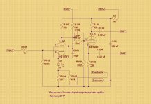
I use a resistor that has at least 10 times resistance than a dynamic resistance of the LED, just to apply feedback to it. Also, as you may see, the LED is above the resistor, so feedback ratio is stable and linear, while dynamic resistance of the LED is negligible against dynamic resistance of the tub e's cathode.
Attachments
There's no rule for me.I am not concerned about the LED distortions, i am concerned about the valve distortions so i came to the conclusion that i prefer the noise of a resistor to the distortions generated by the lack of feedback when you use only led's for bias.Do you put the resistor on the cathode then the LED? How do you determine the value of the resistor? Thanks for the help.
- Home
- Amplifiers
- Tubes / Valves
- LED tube biasing, pros and cons