You can load the LED through a separate network in parallel with the circuit as SY or somebody else if i don't remember well did in his phono preamps.It's also good at start up!Since the current going through it won't vary much at all, the Vf stays constant. So in the real world, tests have shown that using a cheap red LED to get about +1.6V at the cathode of a 12AX7 works fine.
Last edited:
I haven't tried to cross check the V-I curves of LEDs of the same colour, but of a range of models, such as different Mcd ratings (but still in 3mm or 5mm common packages as would typically be used in amps for preamp stages).But not all LEDs are the same. The low current ones will be less affected by low plate currents.
For that type of LED, I would guesstimate that the V-I curves are fairly similar between the different 'efficiency' performance grades - whereby the lumen output could change dramatically between LEDs down at the 0.1-2mA level, but the V-I curve would be somewhat similar.
Last edited:
Important to remember , placing LED in the circuit wont cure any deficiencies or improve anything, it is not a miracle, just technology which is widely available, cheap and reliable.
Dreamth, Can you explain biasing a valve with a led through separate // network? what the heck is that?
Dreamth, Can you explain biasing a valve with a led through separate // network? what the heck is that?
Dreamth, Can you explain biasing a valve with a led through separate // network? what the heck is that?
Something along these lines?
Cheap Red LED bias on ecc83/12ax7
As rongon's link shows, the LED operating current can be increased using any practical dc like supply - such as using the cathode bias voltage from a PP output stage if you have one, or even a simple half-wave rectifier plus cap filter and buffer resistor taken from a heater supply with CT or humdinger to gnd.
As rongon's link shows, the LED operating current can be increased using any practical dc like supply - such as using the cathode bias voltage from a PP output stage if you have one, or even a simple half-wave rectifier plus cap filter and buffer resistor taken from a heater supply with CT or humdinger to gnd.
as with a resistor , i used a input tube with 2ma and 1K cathode resistor and just replace it with a low noise 100ohm film one and run 20ma trough it with the help of derived cathode current from the power tube ( see monkey , free monkey , drd design) no needs of capacitor bypass at this value and less noise than a led ..
Yep, that's what i ment.
Taking a 12AX7, if the triode draws a constant 1mA plate current, that's what will be the LED's If as well. The Ri of the LED may be higher than it would be at If=5mA, but since the current going through it won't vary much at all, the Vf stays constant.
The current through the LED is going to be entirely dependant on the plate voltage chosen. Say you pick an LED to give 1.5v. Plate voltage 90v and LED 1.5v = x mA. Plate voltage 150v, LED 1.5v = x + 1/2x mA. 200v, 1.5v = 2(x) mA. 250v, 1.5v = 2 1/2(x) mA 300v, 1.5v = 3(x) mA. The (x) is the problem. What plate voltage do you have to use for the current you need according to the load line? And does an LED give you the same current that a resistor would give you, as you look at the graph and the grid voltage line for 1.5v? What happens when the LED is just barely above the 1.5v turn on voltage (at very low current) and the grid signal goes to (+) 1v? When does the LED turn off and clip?
Last edited:
In the first statement why not use a single blue led which will be close to the 4v drop?
Originally Posted by rongon
... If your 6J5 has a 1k cathode bias resistor and is drawing 4mA plate current, then you need -4V grid bias, or +4V at the tube's cathode. To achieve that, use two green LEDs in series from the tube's cathode to ground to get +4V at the tube's cathode.
------------------------------
Where did you say your cathode resistor was 1K and the bias was 4v? What is the plate voltage you have? What is the plate current now and resistor?
Important to remember , placing LED in the circuit wont cure any deficiencies or improve anything, it is not a miracle, just technology which is widely available, cheap and reliable.
Dreamth, Can you explain biasing a valve with a led through separate // network? what the heck is that?
Using the LED relieves the necessity of a cathode bypass capacitor, most often an electrolytic.
Originally Posted by rongon
Where did you say your cathode resistor was 1K and the bias was 4v? What is the plate voltage you have? What is the plate current now and resistor?
I did not actually write that.
In my SE amp the bias resistor i replaced was 390 ohms if i recall. and the Kv was 4 or 5, i don't have my notes at home so i am going by memory.
Wave, This would be an interesting experiment. Set up the cathode as it is in the stock amp. He said it had a 390R resistor and had (4.5v). That's @ 10mA of current. Then put 3 LED's in series together with 1.5v drop (4.5v) in parallel to the Rk. What would the Vk be? What would the new total current be?
Last edited:
...shut down the whole stack if one diode goes under turn on?...
Similar parts in series will come to similar voltages. You won't have "one shut down".
Junction diodes in general do not "shut down". A plain Si diode conducts at 0.5V, 0.4V, exponentially over many decades of current.
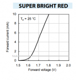
In contrast vacuum tubes are not useful over more than a couple decades of current; and for low THD we normally run them over much-much less than a decade of current. Typically a 3:1 swing will make 5% THD. In the same 3:1 swing the LED(s) will vary around 0.052V, which is "nothing" compared to the several volts static bias.
This is what an LED looks like over the range of currents we might use in small tubes:
Attachments
Here is 12AX7 biased with LED, resistor, and battery (equivalent to a big cap across a resistor). Grid swung +/-2V. Plate and cathode voltages plotted (cathode Vs multiplied by 100 so they show on same scale).
The unbypassed resistor is by far the most linear, but at half the gain of the others.
The LED and the battery (or BFC) lay so close together I can hardly read a difference. The LED bias is a hair down on gain but much less than tube-to-tube variation. Given normally steady supply voltage, there's little to choose.
For extreme variation of B+, the LED (or battery) amounts to fixed bias and will "amplify" supply variation and throw the idle plate voltage into the weeds. Resistor (with or without cap) will self-balance to the change of supply. A 90V-500V change of B+ is ugly at the ends. Normal (wall-power) 280V-330V change is no real difference.
Attachments
You're right PRR! I used all the bias combinations in the past and always found the resistor better than anything else , allthough you have to deal with the lower gain .The resistor is adding some noise, but the distortion reducing mechanism it allows will give lower thd+N when working.
- Home
- Amplifiers
- Tubes / Valves
- LED tube biasing, pros and cons