In this thread I want to share some experiments on a real triode (12AU7), using a homemade curve tracer setup.
One of my main interests was characterize grid current.
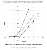
According to my measurements on a 12AU7, when Vgk = 1 V, input impedance is 1.4 kohm. It falls below 1 kohm when Vg = 2.2V. I could not go any further with my current setup. At just 0.5V Vgk, input impedance is close to 2.5 kohm, already very low for almost any previous stage.
This is what I expected.
Do these values match with what you experienced/expected?
Just to illustrate some real values and the simple calculation:
Vgk, Ig[mA]
1.37, 0.76
1.6, 0.9
1.8, 1.13
So, for Vgk = 1.6, input impedance is (1.8-1.37)/(1.13-0.76), in kohms. In this case, 1.16 kohm.
One of my main interests was characterize grid current.
According to my measurements on a 12AU7, when Vgk = 1 V, input impedance is 1.4 kohm. It falls below 1 kohm when Vg = 2.2V. I could not go any further with my current setup. At just 0.5V Vgk, input impedance is close to 2.5 kohm, already very low for almost any previous stage.
This is what I expected.
Do these values match with what you experienced/expected?
Just to illustrate some real values and the simple calculation:
Vgk, Ig[mA]
1.37, 0.76
1.6, 0.9
1.8, 1.13
So, for Vgk = 1.6, input impedance is (1.8-1.37)/(1.13-0.76), in kohms. In this case, 1.16 kohm.
Last edited:
1k-2k seems about right, see Guitar Amplifier Overdrive - Ulrich Neumann, Malcolm Irving - Google Books
Even though this thread was moved by moderator from "tubes/valves" subforum to this one, my aim is to build an A2 hi-fi amplifier.
The next step is to use my curve tracer to characterize 6V6 tubes: anode curves and grid current, to help me in the design of a A2 driver stage (using dual supply rails), and to share information about this.
But probably this topic is not for "Instruments and Amps".
Gnobuddy, for the 12AU7 (~100 Vdc ak) the DC grid current is a little bit higher, which I expected too, as it handles higher anode current.
Just recently I was looking at the datasheet for a 12AB5, which is a 6V6 stuffed into a nine-pin bottle. The datasheet shows curves for positive control grid voltages, up to +15 volts. IIRC (control) grid current was around 20 mA at Vgk = +15 V. DC input resistance around 750 ohms, not too far from the 1k number you mentioned for the 12AU7.The next step is to use my curve tracer to characterize 6V6 tubes: anode curves and grid current
Leonidas Fender never built a guitar amp like that, true. Most DIY valve guitar amps still pay homage to Fender and Marshall amps from half a century ago, also true.to help me in the design of a A2 driver stage (using dual supply rails), and to share information about this.
But probably this topic is not for "Instruments and Amps".
But Tubelab (George) on this forum is one person who has explored AB2 in all sorts of valve amps, including some he used as guitar amps.
In fact, the reason I was looking at 12AB5 datasheets is because I'm in the early planning stages for a guitar amp I want to design and build using a pair of them, driven in AB2 mode using a pair of MOSFETs. I've been impressed by the amount of power Tubelab George has managed to repeatedly squeeze out of the most unlikely tubes, partly by driving them into AB2 mode, and want to see if I can replicate a little of his magic.
I've already made a low-current dual-rail +/- 40 V power supply using a 12.6-0-12.6 transformer. It's intended to power the driver MOSFETs.
I've also already built a second dual-rail transformer using a 120 V:120 V mains isolation transformer, and a voltage doubler. Unloaded, it has +360V and +180V rails, which I'm hoping to use for the anode and screen grid supply voltages respectively. (If 180V isn't enough for the 12AB5 screen grids, I'll use a third MOSFET to drop the 360 V rail down to 250V or so for the screen grids.)
Beyond those basics, our plans may not have a whole lot in common. I will be looking for ways to generate lots of nonlinear distortion, and you, presumably, will be looking for the opposite.
")
-Gnobuddy
A2 operation for the output tube is a different matter, but that was not what you asked... which was for small-signal, i.e., voltage amplification. If you want to move the thread back to the Tubes forum, you can change the thread title or ask the appropriate question.Even though this thread was moved by moderator from "tubes/valves" subforum to this one, my aim is to build an A2 hi-fi amplifier.
The next step is to use my curve tracer to characterize 6V6 tubes: anode curves and grid current, to help me in the design of a A2 driver stage (using dual supply rails), and to share information about this.
But probably this topic is not for "Instruments and Amps".
Gnobuddy, for the 12AU7 (~100 Vdc ak) the DC grid current is a little bit higher, which I expected too, as it handles higher anode current.
I built an amp using the 12AB5 with around 390V on the plates and the regular treatment on the screens. Might be different for AB2 but the tube had no problem with the voltages.Just recently I was looking at the datasheet for a 12AB5, which is a 6V6 stuffed into a nine-pin bottle. <snip>
I found your 12AB5 thread quite a while ago via Google search. Yours was literally the only thread I found describing anyone using these valves for a guitar amp.I built an amp using the 12AB5 with around 390V on the plates and the regular treatment on the screens.
Good to know! Straight-forward class AB operation off the doubled 120 V line transformer will be the backup plan.Might be different for AB2 but the tube had no problem with the voltages.
George posted a while ago about using a pair of 6V6 in push-pull for some 35 watts clean output, using, IIRC, around 340V on the anodes and around half that on the screens, with a 6.6k output transformer and class AB2 drive to the output valves. I'm wondering if the same recipe will work for 12AB5s.
I might do my first AB2 experiment with valves that are more disposable, probably a pair of 12C5s. If I don't blow that one up, I'll try the 12AB5s.
-Gnobuddy
This post is a mix of share + ask for advice.
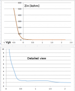
These are approximate, but real measurements of input impedance of a 12AU7.
As most of us know, starting from -0.5V gk, the tube is not an "infinite" input impedance device. Very high, 500 kohm, but still. It falls very quickly to just 20 kohm at 0 V gk, and then from 0.5, it is very close to 1 kohm (gradually falling, as is to be expected).
This is a previous step, before testing power pentodes.
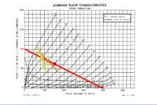
Now, if we wanted to drive a tube into A2, I understand that it is like if the load line steepens gradually while going further into positive grid voltage? (see attachment).
Also, the driver stage has to be able to deliver enough current for that steep load line.
Are this assumptions correct? Any other relevant thing I should look at with my first experiments?
These are approximate, but real measurements of input impedance of a 12AU7.
As most of us know, starting from -0.5V gk, the tube is not an "infinite" input impedance device. Very high, 500 kohm, but still. It falls very quickly to just 20 kohm at 0 V gk, and then from 0.5, it is very close to 1 kohm (gradually falling, as is to be expected).
This is a previous step, before testing power pentodes.
Now, if we wanted to drive a tube into A2, I understand that it is like if the load line steepens gradually while going further into positive grid voltage? (see attachment).
Also, the driver stage has to be able to deliver enough current for that steep load line.
Are this assumptions correct? Any other relevant thing I should look at with my first experiments?
Attachments
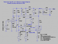
Just wondering, are you familiar with this current thread (about A2 drive using MOSFETs in Hi-Fi amplfiers)? Tubelab Universal Driver Board, 2015 version...my aim is to build an A2 hi-fi amplifier.
Also, the thread I just linked to above was itself a spin-off triggered by discussions on a much older (2008) thread about AB2 operation for Hi-Fi amplifiers: 6L6GC AB2 Amp
Maybe you'll find something helpful on one of those threads. George has even posted the schematic of his MOSFET driver circuit, if you want something ready to use.
-Gnobuddy
For class A2 P-P there is an interesting possibility. I discovered this surprising technique in a LV tube operation thread recently.
Notice from your graph of grid current versus grid voltage how close to linear the current increase is. Now with 2 tubes in class A2 P-P, the sum of the grid currents would be near constant. So use a center tapped interstage xfmr to drive the two grids with a CCS pull-up on the center tap ( of the average sum current ). The driver stage will now only have to supply the mis-tracking between the two "linear" current draw curves. So will be much higher input impedance.
Edcor WSM or XSM matching xfmrs could do this inexpensively.
This obviously makes for a novel way to operate tubes at low B+ voltages, using Class A2 operation to get decent plate currents, without the grid current penalty. An XSM xfmr should allow driving output power stages in P-P class A2 also.
Last edited:
Only if the quiescent operating point was so "hot" that both tubes were biased with the grid quite positive, i.e. deep into (control) grid current flow. For this grid current cancellation trick to work, you would actually have to stay in positive grid voltage territory even on negative signal peaks....how close to linear the current increase is. Now with 2 tubes in class A2 P-P, the sum of the grid currents would be near constant.
That is a bias so hot that the output tubes are limited to operating within quite a small region of their normal characteristic curves.
Doesn't that seem far more limiting than normal AB1 operation? Not to mention, with an ultra-hot bias like that, how are you going to keep the quiescent operating conditions below the maximum anode dissipation curve? You'd have to drop to an absurdly low B+, at which point, output power becomes drastically limited.
I can understand why this mode of operation might work in the weird world of ultra low B+ tube circuitry. Operating entirely in grid current territory is not unusual for these types of circuits.
But I can't see how the "bias it so hot it's always at positive control grid voltage" idea would work well for an audio amp running on anywhere near normal B+ voltage.
To me it makes a lot more sense to just use a MOSFET source-follower to drive the output tube grid. It has a low enough output impedance to comfortably drive the grid positive without difficulty.
-Gnobuddy
All very valid points you make. Certainly for a triode, one would have to operate at rather low plate voltages to keep dissipation (both plate and grid 1) in bounds.
And the usual Mosfet follower/driver for class aB2 makes the best sense for practical __2 operation.
However, the thread begins:
A 26A7 tube could work better for this "always positive" grid1 idea. Since the screen grid can be kept at low voltage to simulate a low plate voltage (as if a triode at LV). Or a TV Sweep Tube operated at below normal plate dissipation and low screen V could work.
One just needs to restore the normal operating current range by lowering Vg2 to compensate for positive Vg1. But be careful not to melt down grid 1 with positive current. A tube intended for positive grid 1 operation (4D32) or one with a big grid 1 cooler fin (40KG6, 6HJ5) should help. Something like 26V to 48V on grid 2.
And the usual Mosfet follower/driver for class aB2 makes the best sense for practical __2 operation.
However, the thread begins:
so I just thought I would mention this off beat idea.Input impedance experimentations
A 26A7 tube could work better for this "always positive" grid1 idea. Since the screen grid can be kept at low voltage to simulate a low plate voltage (as if a triode at LV). Or a TV Sweep Tube operated at below normal plate dissipation and low screen V could work.
One just needs to restore the normal operating current range by lowering Vg2 to compensate for positive Vg1. But be careful not to melt down grid 1 with positive current. A tube intended for positive grid 1 operation (4D32) or one with a big grid 1 cooler fin (40KG6, 6HJ5) should help. Something like 26V to 48V on grid 2.
...for a triode, one would have to operate at rather low plate voltages to keep dissipation (both plate and grid 1) in bounds....
Or a very high Mu.
This was occasionally suggested back in the day. 6A6 data shows a zero-bias condition. The grid impedance has already dropped at zero bias. Under swing, the one side impedance falls while the other side rises, making a non-constant but less-kinky driver load. But note that the grid input is nominally 0.451 Watts, and must face a varying load, so we would want a driver capable of a good Watt easy. The grid impedance gets near 2K at peak swing which will guide our driver transformer (10K CT?).
Type '46 is well documented for zero-bias operation.
3CX1500D7 is rated for zero bias, 0Vgk and at a zippy 3,000V on the plate. (The 500W dissipation is only 1/3rd what this coffee-mug tube is rated for.)
There was a battery-radio tube designed for zero bias and low idle current with reasonably constant Zin in such condition. Dang if I remember which one. Maybe 1/3rd of a Watt?
Last edited:
Type 52 tube got some mention here:
http://www.diyaudio.com/forums/tubes-valves/300185-question-type-52-tube-2.html#post4908355
If one has the internal Mu factor between grid 2 and grid 1 of some pentode, then the input V range should be translatable by shifting Vg2 accordingly. And watching grid 1 dissipation for safety max.
http://www.diyaudio.com/forums/tubes-valves/300185-question-type-52-tube-2.html#post4908355
If one has the internal Mu factor between grid 2 and grid 1 of some pentode, then the input V range should be translatable by shifting Vg2 accordingly. And watching grid 1 dissipation for safety max.
Last edited:
Following Gnobuddy's advice, I considered a MOSFET driver stage. As I like to do, I started from the begining, with a minimalist design.
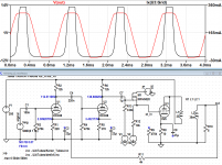
I simulated a simple 6V6 amplifier, and it seems to works great (as expected) bumping up from 1W (single ended triode, A1) to 4.4W(< 0.4% THD, A2).
The problem is that, a strong enough signal makes de output tube's grid more and more positive, with no limit (until MOSFET supply voltage is almost reached)., and the max grid dissipation will surely be surpassed. The sensitivity is around 0.6 V pk, but for 1V pk input signal (not that high), the output tube drive signal is overkill. Just look at the simulation attached: 300 mA grid current !!
I read some interesting information about this kind of circuits, like MOSFET Follies, a book, some threads around,... and a high voltage bipolar supply is usualy used for the driver stage (be it MOSFET or tube), and no limiting mechanism.
How can I avoid a strong signal to basically destroy the output tube's grid (and even the MOSFET, if not properly heatsinked)?
The only workaround I found is to use a +25V/-70V supply for the driver. This way, the grid signal clips at a safe voltage, much the same as when it clips at 0V when using a common A1 driver stage, and I get plenty of clean power.
Suggestion?
Attachments
Credit where due: George (Tubelab_com) was doing this long before I had the same idea. I only got interested in valves around 2010 or so, shortly after I got back into playing guitar. Once I'd encountered the problem of blocking distortion, I thought about using a MOSFET direct-coupled to the output valve grids, Googled it, and found links to George's website. George had already been doing it for years in multiple designs of his own.Following Gnobuddy's advice...
Poke around diyAudio, there are tons of posts by George involving MOSFET drivers and class AB2 operation, including schematics of most of his designs, measurement data, 'scope shots, etc, etc.
This is okay for Hi-Fi, where the output is never intentionally driven into clipping.... a high voltage bipolar supply is usualy used for the driver stage (be it MOSFET or tube), and no limiting mechanism.
But for guitar, I too think that something else is required.
This seems like a perfectly reasonable solution to me.The only workaround I found is to use a +25V/-70V supply for the driver.

For my own project (a guitar amp in the very early conceptual stage), I had two solutions in mind. The first is exactly what you described, limiting MOSFET drain supply voltage (to about 15 - 18 volts in my case.)
The second solution I was considering is simply inserting a resistor between MOSFET drain and the MOSFET positive supply rail. The resistor value will be chosen so the MOSFET saturates due to limited Vds before the output valve grids become overdriven to the point of overdissipation. There should be minimal effect on distortion, as the MOSFET is relatively insensitive to changes in drain voltage.
There is the question of MOSFET reverse transfer capacitance (Cgd or Crss), which can vary with drain-to-source voltage, especially at relatively low values of Vds. Given the nonlinearity of the valves in the amp, I have my doubts that tiny variations in Crss will affect the amplifiers distortion performance to any significant extent, but it may be something to keep in mind, at least until you know it's not a problem.
As a third alternative, in a post a couple of months ago, George mentioned using 1k grid stoppers for the output pentodes in a test-bench prototype, driven by his MOSFET driver board. Since these resistors sit between the driver MOSFET source and the output valve control grid, nonlinear grid current through them does affect THD significantly once into the region of positive control grid voltage.
George found that it took about 15 mA of current flow into the control grids of those particular output valves to achieve full power at the output, and those 15 mA of non-linear current flow through the 1k resistor added a fair amount of distortion to the amplifier, progressively increasing with drive signal level. Which may be okay, or even good, in a guitar amp - many guitarists want progressively increasing distortion to create touch-sensitive amp response.
Obviously, this is not a good idea for a Hi-Fi amplifier.
-Gnobuddy
The resistor in the Mosfet Drain plus a Zener from cathode to grid should stop any overdrive. Suggest using the smallest Mosfet (low Crss) that will do the job.
You would need to know the grid current curve reliably with just the Drain resistor (may change with tube ageing), so the Zener is an insurance policy.
Gets used for Crazy/Twin Drive protection.
If you are experimenting with positive grid drive, don't forget there is also the possibility of using a current drive of the positive grid. Crazy/Twin Drive uses this for grid 1. (Screen grid V likely will need adjusting down for positive grid only type drives) One can make vacuum tube current mirrors this way.
Last edited:
- Status
- This old topic is closed. If you want to reopen this topic, contact a moderator using the "Report Post" button.
- Home
- Amplifiers
- Tubes / Valves
- Input impedance experimentations, aiming to build an A2 stage