OK, the formula for figuring out voltage to dB is
dB = 20 x Log(volts1/volts2)
So in my case, that's
dB = 20 x Log(6.2/281.9)
dB = -33.15
Or on the calculator:
* 6.2 / 281.9
* Hit enter
* Hit log10 button
* Multiply by 20
* = -33.15
The ripple at the rectifier output is -33.15 dB down from Edc.
If we want to go for the standard -90 dB, that's another -56.85 dB.
Let's round to 57.
To figure out the smoothing factor required to achieve that, it's:
Fs = 10^(Fs[dBv]/20)
On the calculator
* 57/20 = 2.85
* Hit 10^x button
* 707.95
So let's say I need a smoothing factor of 708 to reach a target ripple of -90 dB below Edc.
First of all, do these calculations seem correct?
Second, do you think that would be enough PSRR for a headphone amp?
Cans are Grado SR125 (32 ohm, 98 dB SPL for 1mV input).
Last edited:
Now to get back to what PRR said in Post #4 about peak current being limited by transformer resistance, the rather high 419 ohm DCR of the PT secondary seems to be a major help. In PSUD2, I'm able to model the PS using a 20uF input cap (which the rectifier would see with two 10uF units after the rail split, as I mentioned in post #1) and 100uF caps after the choke and the RC filter, and it does just fine. If I increase the 100uF caps to 200uF, it still does just fine. So unless I'm doing something wrong here, it's OK to exceed that 10uF input cap limit on the datasheet and to use some larger caps throughout the PS network.
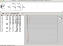
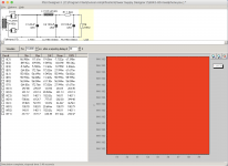
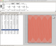
Adjusting the end resistor value in PSUD2 to 2.5k, at rongon's suggestion, we get a nice curve up to stability, with no ringing, settling right in at 140V (first screenshot).
If we allow a 30 second delay and run the sim for 10 seconds, it sits at 140V with a ripple of 152.82uV (second screenshot).
I'm sure there are ways to fine-tune this, but for now I'm glad to know that I can safely make a first iteration of this amp using parts I have (unless someone sees any mistakes I'm making).
Attachments
Last edited:
Calculating ripple reduction manually with LCRC sections as above (10H -- 100uF -- 1.8K -- 100uF):
LC Section Fs1 = (2 x pi x (2 x 60Hz))^2 x 10H x 100uF -1 = 567.5
RC Section Fs2 = 2 x pi x (2 x 60Hz) x 1800R x 100uF +1 = 136.48
Fst = Fs1 x Fs2 = 77547.74
77547.74 seems like a really high ripple reduction factor to me.
In dBv, it translates to 20 x Log(77547.74) = -97.79 dBv
That also leaves out whatever ripple attenuation would be provided by the 10uF input cap.
So, more than the target of -90 dB
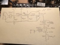
In terms of voltage reduction, I calculated 281.9V output from the rectifier. Target B+ is 146V, so a drop of 143.1V is required. In a split-rail PS and 18mA on the 5842s, that would require a total resistance of R = V/I = 143.1/.018 = 7.95K in each channel.
That means that the series resistance of the network would need to be much greater than what is shown in the PSUD2 model (which admittedly might have been set up incorrectly). If I kept the 2-stage design, one channel would look like:
10uF -- 10H/414R -- 100uF -- 7.5K -- 100uF
DHTRob's "Classic" schematic (post #7) does show a 10K 5watt resistor in that position, so the value is not necessarily extreme (the fallacy of appeal to authority).
On a hunch, I went back to PSUD2 and changed the load to current sink @ 18mA, on rongon's suggestion. To get 146V without an error message (current sink causing negative voltage on startup), I have to reduce the 100uF caps to 50uF and use a 9.4K resistor -- very close to the 10K in Rob's "classic" schemo. That's 2K more than my manual calculation, but closer than the 7.6K difference from the earlier PSUD sim with a resistive load (and 1.8k resistor in the last position).
So, which do I trust? My calculations or PSUD2?")
LC Section Fs1 = (2 x pi x (2 x 60Hz))^2 x 10H x 100uF -1 = 567.5
RC Section Fs2 = 2 x pi x (2 x 60Hz) x 1800R x 100uF +1 = 136.48
Fst = Fs1 x Fs2 = 77547.74
77547.74 seems like a really high ripple reduction factor to me.
In dBv, it translates to 20 x Log(77547.74) = -97.79 dBv
That also leaves out whatever ripple attenuation would be provided by the 10uF input cap.
So, more than the target of -90 dB
In terms of voltage reduction, I calculated 281.9V output from the rectifier. Target B+ is 146V, so a drop of 143.1V is required. In a split-rail PS and 18mA on the 5842s, that would require a total resistance of R = V/I = 143.1/.018 = 7.95K in each channel.
That means that the series resistance of the network would need to be much greater than what is shown in the PSUD2 model (which admittedly might have been set up incorrectly). If I kept the 2-stage design, one channel would look like:
10uF -- 10H/414R -- 100uF -- 7.5K -- 100uF
DHTRob's "Classic" schematic (post #7) does show a 10K 5watt resistor in that position, so the value is not necessarily extreme (the fallacy of appeal to authority).
On a hunch, I went back to PSUD2 and changed the load to current sink @ 18mA, on rongon's suggestion. To get 146V without an error message (current sink causing negative voltage on startup), I have to reduce the 100uF caps to 50uF and use a 9.4K resistor -- very close to the 10K in Rob's "classic" schemo. That's 2K more than my manual calculation, but closer than the 7.6K difference from the earlier PSUD sim with a resistive load (and 1.8k resistor in the last position).
So, which do I trust? My calculations or PSUD2?
Last edited:
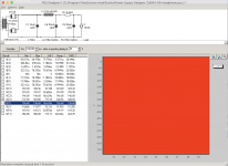
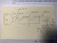
Target B+ of 146.6V. PSUD2 screenshot and hand calculation schematics attached. Difference is 9.4K final resistor in PSUD2, 7.1K final resistor in hand calc. Think I'm leaning toward hand calc.
Do these seem reasonable or ill-advised?
Do these seem reasonable or ill-advised?
Attachments
Last edited:
Another possibility is to have a single rail PS, placing the chokes in series with lower value caps, and splitting into separate channels before the final dropping resistors.
10uf -- 10H/414R -- 10H/414R -- (channel split) -- 5.8K -- 10uF (x2)
B+ is 146.6V in each channel; reduction factor is 356,688.58 or -111 dB, the best value so far.
I had wanted the split right after the rectifier so that the two supply rails could respond more dynamically to the music in each channel. Not sure if it would really make an audible difference.
Attachments
So, I'm using the Raphaelite OP5.5K5A OPT (Raphaelite 5W single-ended output transformer OP5.5K5A 6V6 EL84 sealed | eBay), which is 5.5K into 8 or 32ohm. I need to wire it for 32ohm and am wondering how to do that. It has two 16 ohm secondaries.
As far as I can tell there is no owner's manual available. Pinout groupings are as follows:
Pin 2 -- B+
Pin 10 -- Plate
Pin 6 -- Ground
Pin 5 -- 16ohm
Pin 4 -- 0
Pin 8 -- 16ohm
Pin 7 -- 0
For 32 ohm, I'd need to wire the two 16 ohm secondaries in series, so how would that work? Would I simply wire the two secondary groupings like this?
5 --> 4 --> 8 --> 7, where 5 goes to the signal tab on the headphone jack and 7 goes to the common tab?
Last edited:
I've got everything wired up and running at good voltages for a starting point, but am not getting any sound. My guess is either that I miswired the OPT secondary or the headphone jack.
B+ = 148V
Va = 142V
Vk = 2V
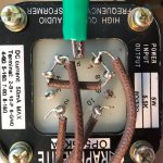
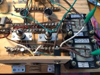
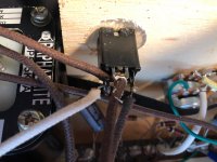
Here's a pic of the OPT secondary wiring. It follows the diagram in the previous post. Seem OK?
B+ = 148V
Va = 142V
Vk = 2V
Here's a pic of the OPT secondary wiring. It follows the diagram in the previous post. Seem OK?
Attachments
Could be. I've got pin 7 connected to ground anyway.
Thanks to jazbo8's suggestion, I have sound, though at first it was only in one channel, which I traced to a headphone jack tab that wasn't making contact with the right channel. Swapped in a new one and we have stereo.
Now I need a lot more hum attenuation and possibly switch to DC heater supply.
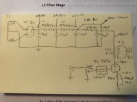
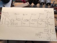
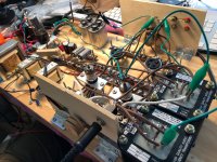
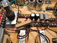
The PT I was going to use went bad so I ordered one with more appropriate voltage, Hammond 269EX (380VCT). Using a 5Y3GT. Schemo and some pics attached. I'm going to add another 22uf cap and also shift the dropping resistance to the final leg, as that might do more for attenuation.
Edit: I just shifted the 10uF cap in front of the 330R resistor and added a 22uF one there. Not much noise reduction but after listening a little longer it appears my volume pot (a cheap Alpha 100K) has bad connectivity. Lots of crunching and sudden volume change in the right channel when i adjust it. Right channel noticeably quieter than left. Also the headphone jack has spotty connectivity.
Thanks to jazbo8's suggestion, I have sound, though at first it was only in one channel, which I traced to a headphone jack tab that wasn't making contact with the right channel. Swapped in a new one and we have stereo.
Now I need a lot more hum attenuation and possibly switch to DC heater supply.
The PT I was going to use went bad so I ordered one with more appropriate voltage, Hammond 269EX (380VCT). Using a 5Y3GT. Schemo and some pics attached. I'm going to add another 22uf cap and also shift the dropping resistance to the final leg, as that might do more for attenuation.
Edit: I just shifted the 10uF cap in front of the 330R resistor and added a 22uF one there. Not much noise reduction but after listening a little longer it appears my volume pot (a cheap Alpha 100K) has bad connectivity. Lots of crunching and sudden volume change in the right channel when i adjust it. Right channel noticeably quieter than left. Also the headphone jack has spotty connectivity.
Attachments
Last edited:
.... Now I need a lot more hum attenuation and possibly switch to DC heater supply. .....
Probably unrelated, but I would consider connecting those 200 ohm resistors in series with the grid of the 5842 as close to the tube socket pin as practicable. I assume they are to break potential spurious oscillations, but I don't know that you get much benefit of that when they are so far from the tube. Keep the lead from the resistor body to its tube pin as short as practicable. I think the grid is pinned out to two or more separate pins.
I would be interested in what you think of those OPT's when / if you have formed an opinion on them.
Win W5JAG
Thanks for the suggestion. It’s difficult to do that on the breadboard, but when the final build is soldered they’ll certainly be very close.
I’m going to try it with just one connected as well, just to see. There are four pins to grid, and DHTRob, who’s design I started with, used all four to get rid of “HF nastiness.”
Also, I did some more listening and the noise is definitely related to the volume pot. There are positions where the noise goes away and the music is crystal clear. Bummer. It didn’t do this last time I used it.
Last edited:
Posting an updated schematic. I rearranged the power supply, removing the initial dropping resistor and placing a 1.3K in each channel at the end. It sounds much better, and any noise issues are being caused by the faulty volume pot.
Right channel is still nearly silent and makes crackles when I turn the volume knob, occasionally coming through at normal volume for a second or two, like when my electric guitar cable is going bad or poorly plugged. So I guess it could still be the socket it happens when manipulating the knob.
Right channel is still nearly silent and makes crackles when I turn the volume knob, occasionally coming through at normal volume for a second or two, like when my electric guitar cable is going bad or poorly plugged. So I guess it could still be the socket it happens when manipulating the knob.
Attachments
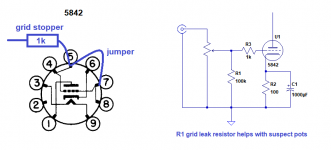
On 5842, pins 4,5,7 and 8 all go to the grid.
There are some high-gm RF tubes that have two pins going to the cathode. Apparently for audio use these are best strapped together, and then treated as one connection. Otherwise there are problems with oscillations or increased harmonic distortion.
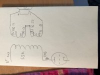
With the above in mind, you might try placing a jumper from pins 5 to 7, and connecting a single grid stopper resistor to only one pin. Like in the picture on the left in the attached graphic.
Also, you don't have a grid leak resistor installed. You're relying on the potentiometer to be the grid leak. If that goes open, or shorts, it will cause all sorts of problems for the 5842 grid. Add R1 as in the picture on the right in the attachment. That's a proper grid leak resistor. If installed as pictured, it will keep a proper load on the grid even if the potentiometer fails open (which is how they usually fail). It's not a cure for a failing pot, but it's good insurance for the tube.
--
There are some high-gm RF tubes that have two pins going to the cathode. Apparently for audio use these are best strapped together, and then treated as one connection. Otherwise there are problems with oscillations or increased harmonic distortion.
With the above in mind, you might try placing a jumper from pins 5 to 7, and connecting a single grid stopper resistor to only one pin. Like in the picture on the left in the attached graphic.
Also, you don't have a grid leak resistor installed. You're relying on the potentiometer to be the grid leak. If that goes open, or shorts, it will cause all sorts of problems for the 5842 grid. Add R1 as in the picture on the right in the attachment. That's a proper grid leak resistor. If installed as pictured, it will keep a proper load on the grid even if the potentiometer fails open (which is how they usually fail). It's not a cure for a failing pot, but it's good insurance for the tube.
--
Attachments
I have found grid stoppers aren't always enough and I tend to use a RC combination. Clearly it needs to let audio through without restriction but stop RF.
I designed a hybrid valve/chip amp and when the chip amp oscillated at about 1MHZ it radiated back into the valve grid and all I had was an oscillator. An RC fixed it then I could look for a fix for the chip amp.
Its very good practice to put the grid stopper hard up against the valve.
Any inputs on valve amps should be as short as possible and away from heater and HVAC and transformers. Screened input wires are good practice.
If you use a pcb then a copper pour connected to zero volts around the valve is good practice.
I also found decoupling each valve power supply helped with feedback problems.
If there is any DC going through pot you will get crackling when you rotate it. You might need a coupling capacitor before the pot to get rid of DC.
I designed a hybrid valve/chip amp and when the chip amp oscillated at about 1MHZ it radiated back into the valve grid and all I had was an oscillator. An RC fixed it then I could look for a fix for the chip amp.
Its very good practice to put the grid stopper hard up against the valve.
Any inputs on valve amps should be as short as possible and away from heater and HVAC and transformers. Screened input wires are good practice.
If you use a pcb then a copper pour connected to zero volts around the valve is good practice.
I also found decoupling each valve power supply helped with feedback problems.
Right channel is still nearly silent and makes crackles when I turn the volume knob, occasionally coming through at normal volume for a second or two, like when my electric guitar cable is going bad or poorly plugged. So I guess it could still be the socket it happens when manipulating the knob.
If there is any DC going through pot you will get crackling when you rotate it. You might need a coupling capacitor before the pot to get rid of DC.
Thanks rongon and Nigel. I will definitely add a grid leak resistor and try a coupling cap.
After a bit of trial and error I figured out that I'd miswired the headphone socket. Now that's sorted and the sound is nicely balanced.
What's weird is that I get loud hum plus crackling when I manipulate the volume knob, but hum and crackling disappear when it's at the very highest setting. I hear only a faint trace of AC hum if I pause the music and listen for it. So until I get another pot tomorrow the amp is running at full volume, controlling it with my Mac's volume control.
Win: Too early for an assessment of the OPTs since they're breaking in, but they sound nice so far. Plenty of detail and frequency extension. I think they'll improve even more once I find the best operating point for the 5842s.
Attachments
Last edited:
The 100K grid leak resistors attenuated (but didn't eliminate) the crackling but the pot still hums loudly in any position other than farthest right, so it has to go. I did some playing around with op points today.
With 100 ohm carbon film Rk and:
820 ohm wirewound cement dropping resistor:
B+ 155
Va 147
Vk 2.1 (21mA)
Sounds a little better -- more present and balanced, background instruments better mixed into the presentation.
360 ohm carbon composition dropping resistor:
B+ 159
Va 151
Vk 2.2 (22mA)
Much improved sound -- more detailed and dynamic, more present
With 62 ohm carbon comp Rk and 360 ohm carbon comp dropping resistor:
B+ 144
Va 135.5
Vk 1.7
Not as dynamic as the second condition above but more musical and detailed. Something about the carbon comp Rk seems right here.
I acquired an EZ81 rectifier to try higher voltage op points. I think those will really sing with this last selection of components.
- Status
- This old topic is closed. If you want to reopen this topic, contact a moderator using the "Report Post" button.
- Home
- Amplifiers
- Tubes / Valves
- 5842 Headphone Amp