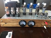
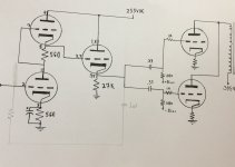
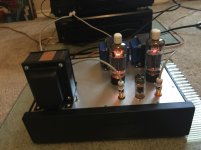
I built this last week. Overall, I’m pretty happy with it, but I’d be open to front end suggestions. To answer the first question from most, the CF is there because this is a recycled top plate and I had a spare hole. I tried an anode follower using 12AX7 into the CF, but it sounded thin to me. I really like the 6829 used here for both SRPP and CF duty.
Someone suggested direct coupling and skipping the coupling caps after the CF, but I thought I’d check here before trying that.
Lastly, I need to upgrade the output iron to something that will handle 150-200mA vs the marginal edcors I’m using and am looking for suggestions. I’d like to go mid range in price and not magnequest, etc.
Thought I’d share the work and ask a few questions at the same time.
Cheers!
Attachments
How deep is your negative rail? You could cap couple the front end to the CF, and DC couple the CF to the output grids. Much better use than driving input caps.
Also, maybe convert the front end to a mu follower, it will sound great and give lower THD than the often misused SRPP. Just my two cents.
Also, maybe convert the front end to a mu follower, it will sound great and give lower THD than the often misused SRPP. Just my two cents.
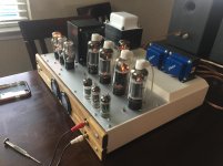
That amp looks real nice.
The 6CB5A Beam Power tube has a screen.
What is the screen voltage?
The maximum rating for the screen is 220V.
(it might be OK for a little more voltage if the tube is triode wired)
The maximum rating for the screen is 4 Watts.
How is the screen connected in your circuit?
Are you running 44mA per channel, or do the meter scales represent a single tube at a time?
I would rather use 4 coupling caps than use 4 CFs.
And I do like the fact that you are biasing each output tube individually.
If you do DC couple, then you could use individual self bias resistors with individual bypass caps (but then you would need more B+ to make up for the 77V self bias).
Last edited:
Nice looking build.
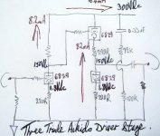
The three triode Aikido cathode follower would improve your cathode folower performance quite a bit.
The 6829 triode is close in performance to the 5965 which I like very much and my figures are lifted directly off the Tubecad Aikido pdf.
The three triode Aikido cathode follower would improve your cathode folower performance quite a bit.
The 6829 triode is close in performance to the 5965 which I like very much and my figures are lifted directly off the Tubecad Aikido pdf.
Attachments
That amp looks real nice. <snip>
The screens are triode connected to the plates. I just drew them in as triodes because I’m lazy.
")
It’s 44mA per tube with a switch to test each set.
Nice looking build.
The three triode Aikido cathode follower would improve your cathode folower performance quite a bit.
The 6829 triode is close in performance to the 5965 which I like very much and my figures are lifted directly off the Tubecad Aikido pdf.
I’ve built that circuit with 12AU7s which is the tube John used in his sample I believe. I remember liking it, so it may be worth a shot. Thanks!
I've got a pair of these that I've been slowly looking for a schematic for. Can you clarify the bias point you've got? Is it 44mA @ -77V on the grid. Did you try running them single ended as well?
Don't mean to derail, there just isn't a ton of info for these tubes out there.
Don't mean to derail, there just isn't a ton of info for these tubes out there.
This is single ended, but with two tubes in parallel.
“Is it 44mA @ -77V on the grid.”
One thing I did vs. most SE schematics is grid bias vs. cathode bias. At any rate, the original schematic I found has the tubes biased around 70mA per tube which I found to be right on the corner of red plating in some cases. I like them backed off to 400V B+ (plate) and 55-60mA bias point to keep them at around 70% PD.
Thanks for the insight! I meant "single single-ended" rather than parallel single-ended (I recognize it isn't PP here). Not that it makes a difference in bias, just wondering what motivated the PSE approach. Maybe it was just the extra octal holes in the chassis though
In building a mental picture of where these tubes like to sit, I've looked through the Thomas Mayer amps and (cathode) bias points but those are the only other example I've seen documented. Admittedly I'm casually 'researching', not digging too much until I come across a pair of OPTs that need a home.
In building a mental picture of where these tubes like to sit, I've looked through the Thomas Mayer amps and (cathode) bias points but those are the only other example I've seen documented. Admittedly I'm casually 'researching', not digging too much until I come across a pair of OPTs that need a home.
Logical question.
Yes, I’ve done about a dozen single tube SE amps with 6CB5A. I think they seem to like a 1.2-1.3K cathode resistor vs the 1K which seems to want to red plate the tubes at 400V B+. It used to be a great option. Not that the 6CB5 is a poor choice, but they are getting scarce so this may be the last one I do.
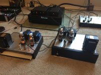
The motivation for this was that I had a set of 2.5K outputs, a top plate, and about seven 6CB5A tubes. I wanted to try grid bias so I could make a more “plug n’ play” option with various 6CB5 tubes. As you can see in the picture, one of them is different.
Yes, I’ve done about a dozen single tube SE amps with 6CB5A. I think they seem to like a 1.2-1.3K cathode resistor vs the 1K which seems to want to red plate the tubes at 400V B+. It used to be a great option. Not that the 6CB5 is a poor choice, but they are getting scarce so this may be the last one I do.
The motivation for this was that I had a set of 2.5K outputs, a top plate, and about seven 6CB5A tubes. I wanted to try grid bias so I could make a more “plug n’ play” option with various 6CB5 tubes. As you can see in the picture, one of them is different.

- Status
- This old topic is closed. If you want to reopen this topic, contact a moderator using the "Report Post" button.
- Home
- Amplifiers
- Tubes / Valves
- PSE 6CB5A Build