Hi
Working on a schematic for a E80CC/KT88 SE UL amp,and I thougt this might be my thread for newbie questions. I know there are quite a few of threads like this but it takes time to search for just the right answer, so I hope you’d bear with me.
I am using the KT88 in SE UL mode, it should give sufficient power and has rather nice distortion numbers.
When in UL mode with g2 at the 40 % tap, how do I find the current passing in it? Read somewhere that the relation between Ik and Ig2 would be fairly constant across different operating points, and this gave a fair approximation? JJ states 140/7 mA, which is 5%
Also, calculating output power with a 3,5k OPT gave 10,5W, using formula P=V2/R. Not considering OPT losses, but still seems a little low for UL?
....how do I find the current passing in it?
...Also, calculating output power with a 3,5k OPT gave 10,5W, using formula P=V2/R. ...
Why do you care what Ig2 is? It is surely "small" compared to Ip.
Show your math on that power computation. What "V"? or "V2"?
The DC dissipation is related to, but not the same, as the sine audio power output.
The audio output for class A is at-most 50% of the idle dissipation. For a 40W tube, 20W. For a real tube, 40% is doing very good, so 16W out. For real tubes with real transformers, working 6550 at 39W dissipation I got 13W clean and 17W with guitar-tolerable THD. For a less aggressive condition 10W might be what it does.
Hi
I’ve got the tubedata, do not remember whose it is but I suppose that’s not important.
The reason for asking was it ads to the total current, needed to know to calculate Rk... Anyhow, I just went with what the diagram said. Every circuit I’ve seen just connect r2 to the UL tap, maybe a with a grid stopper but nothing else.
Tried different Zopt, appearantly approx 2k is a sweetspot between power and 2nd h. distortion. With 2k I should be able to get 14-15W in UL mode. 3,5k lowered it to 10,5 W not considering OPT losses, those are triode territory if I’m mistaking...
Have to run for now.
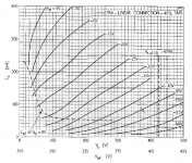
Sure they areRight, I see you mean, the datasheet's UL figures are for push-pull, not really suitable for SE.
") but only for a supply voltage of 425V
but only for a supply voltage of 425V 
Mona
Attachments
Well, I didn’t know that�� I’ve got it at 300V/Vg1 -35, with a 2k OPT. Never paid too much attention to the dotted line at 425V, doesn’t look so UL over there.....
Do I need to start over or might this work? Suppose g2 voltage would change the picture quite a bit?
Do I need to start over or might this work? Suppose g2 voltage would change the picture quite a bit?
Well, I thought so too, but now I am not so sure anymore. I’ve drawn loadlines, made calculations etc, everything worked out quite nice actually. About to start looking at a power supply this evening.
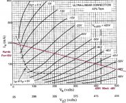
So just to make sure, can I still use these data even though my working point is at a much lower Vq?
And another thing; below the Va line there is a line for Vg2 and Va=300 V corresponds to 375 V Vg2. Is this the voltage ratio between Va and Vg2 at this given operating point?
So just to make sure, can I still use these data even though my working point is at a much lower Vq?
And another thing; below the Va line there is a line for Vg2 and Va=300 V corresponds to 375 V Vg2. Is this the voltage ratio between Va and Vg2 at this given operating point?
I have to disagreeYes, the same characteristic can be used. In your case, Va = Vg2 = 300V at idle.
With other Vg2 (40% of the drop from 300V not 425V) the curves end up much lower (current).For every supply voltage (and tap %) there is another set of curves.
Mona
Attachments
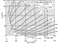
That is one reason why UL is so hard to predict. Need more sets of UL curves at different screen voltages.
Or try and use another mode (Pentode or Triode wired).
Even some old manufacturers of tube curves, i.e. 6L6 and 807 have multiple sets of pentode curves that are for screen voltages of 150, 200, 250, 300V. It makes it easy, just make your choice of screen voltage, and quiescent conditions, and draw a load line.
You can get some ball park numbers of what kind of power you will get:
Look up and down the load line, and see the peak watts from quiescent bias to 0V grid (Delta Vp/Load Z), and peak watts from quiescent bias to 2 times quiescent bias (Delta Vp/Load Z). Then you can easily calculate the approximate results for single ended, or for push pull.
Suppose from quiescent bias to 0V the plate volt change into the plate load is 12 (peak) Watts, and from quiescent bias to 2x quiescent bias the plate voltage change is 4 (peak) Watts.
For single ended, you get (12 + 4)/2 = 8 peak watts , and ((12 + 4)/2)/2 = 4 Watts rms (but of course at very high distortion for this made up example). This will have dominant 2nd harmonic distortion.
Then for push pull, if you use a plate to plate impedance = 2x the (SE) load line, then the peak Watts is 12 + 4 = 16 Watts. That is 8 Watts rms.
The distortion of this made up example will be far less than for the SE mode.
But it will be dominant 3rd harmonic distortion.
These are over simplifications, but make for quick estimation of results.
This also works for SE and Push Pull triode wired mode, if you can find a single set of triode wired curves for your favorite Pentode or favorite Beam Power tube. And for triode wired curves, you only need one set (you do not need a separate set for 150V, 200V, 250V, 300V on the screen, because the plate and screen voltage are always the same (except for a very low voltage drop through a (i.e. 100 Ohm) screen stopper resistor).
Pick your quiescent state, draw a load line, and Go!
Last edited:
Hmm, ok, guess I stepped in a rookie-trap there... Is it possible to make an estimate on Iq based on the ratio 425Va/300Va? If things change fairly linearly will Iq change in direct proportion to the voltage difference? I’m suspecting it won’t... The datasheets have curves for different Vg2 in pentode mode, and it doesn’t look like there’s to much predictability.
Since I will probably order a lot of stuff from overseas, Edcor transformers for example, I want to be sure I have something that might work ok going on.
Maybe triode mode will be the easy way out, but I liked the idea of the extra power with ok distortion numbers...
Since I will probably order a lot of stuff from overseas, Edcor transformers for example, I want to be sure I have something that might work ok going on.
Maybe triode mode will be the easy way out, but I liked the idea of the extra power with ok distortion numbers...
That is one reason why UL is so hard to predict. ....
Why "predict"?
Design a straight Pentode stage only with Vg2=Vp. Use that bias and load, but buy the OT with a UL tap. Try both ways. (And also Triode; solder is cheap.)
Yes, the Pentode will NEED a heap of NFB. But UL usually needs more than just UL NFB, so no change there.
One thing is that a Pentode can usually run Vg2 lower than Vp, with savings of Ig2 and G1 drive. The tap-UL can't. There is a form with a tertiary winding for G2 but nobody does that.
- Status
- This old topic is closed. If you want to reopen this topic, contact a moderator using the "Report Post" button.
- Home
- Amplifiers
- Tubes / Valves
- E80CC/KT88 SE Triode/UL question