Hi guys.
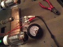
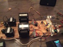
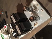
So I have breadboarded this thing together as you can see. Had a few issues at the initial startup, and theres still a few problems to be sorted.
Had to deal with runaway on the output tubes, had to change gridleaks to 56k to get control of it the amp. I am hoping it is something the getter will fix as I get some hours on it, and that I can change them to at least 100k or bigger.
Also has hum I have to figure out, but I am on track of fixing that to(I hope).
Hum and noise varies as I touch and move wires, but for brief moments it plays clear and hum free so I think I am on to something good here!")
So I have breadboarded this thing together as you can see. Had a few issues at the initial startup, and theres still a few problems to be sorted.
Had to deal with runaway on the output tubes, had to change gridleaks to 56k to get control of it the amp. I am hoping it is something the getter will fix as I get some hours on it, and that I can change them to at least 100k or bigger.
Also has hum I have to figure out, but I am on track of fixing that to(I hope).
Hum and noise varies as I touch and move wires, but for brief moments it plays clear and hum free so I think I am on to something good here!
Attachments
Viking83,
For the circuit in your post #24, I suggest the following:
Use a series pair of 100 Ohm resistors across the 6.3V secondary, and ground the center junction of those resistors.
Your filament circuit should not have any contribution to hum, unless you have either an input tube or an output tube that is leaky from filament to cathode. In that case, replace the leaky tube.
You are more likely to have hum due to either a ground loop; bad wiring dress; improper orientation of choke and power transformer versus the output transformer; and spacing from choke and power transformer to the output transformer; or too much ripple in the B+ power supply.
I regularly get less than 100uV hum (0.1 millivolt) at the 4 or 8 Ohm output of my amplifiers, when loaded with an 8 Ohm resistor.
Last edited:
My first test will be the center tap with 2 R100 resistors, and then Ill go from there.
My ripple should be a couple of mV if I remember my calculations correct, and I have gone over my soldering and it looks ok to me... I use one ground bus for everything, and it ends up in the earth ground pin in the cable. I have tried disconnecting the earth, without any luck.
When I disconnect the cable it plays beautifully without hum or anything until the caps have emptied
The hum/noise also varies quite a lot when I touch different wires.
My plan is to fix the heater ground, shield the heater wires, make a proper star ground, shorten and shield signal wires.
Viking83,
Be careful how you connect the first B+ filter cap.
The B+ secondary center tap needs to go Directly to the negative terminal of the first filter cap. Make this as short of a loop as possible.
Then connect a Separate wire from the negative terminal of the first filter cap to the negative terminal of the 2nd filter cap.
Then connect a Separate wire from the negative terminal of the 2nd filter cap to the star ground.
What you do Not want to do is connect the center tap Directly to the star ground, and you do Not want to connect the negative terminal of the first filter cap directly to the star ground.
This is not just a case of the ripple voltage, it is a case of preventing a ground loop that will introduce hum into all the tube stages, including the most sensitive one, the input stage.
Last edited:
Hello from Greece! I built a similar amp with 6n1p-kt120 SE.based on Mikael Abdellah circuit. I used the similar tecnique,of built of ground bus.All the grounded components soldered on the grounded bus,and power capacitors. I use ss rectification and pi filter (300uf 10H 200uf).My power transformer is 330v 0.3 A( no CT) 6.3v 6.6A. dc out about 420v . The ground bus start at first power capacitor,and this point is connected via 10ohm resistor in parallel 0.47uf capacitor in one point in metal chassis. At this point connected the mains ground wire.The rca input ground has not electrical connection with metal chassis.At the first i have a litlle hum.After this i use floating dc in the filaments about 60v,via divider 235kohm-50kohm,connect in filament circuit.No hum at all after this,it is dead silent!!
Thanks for your tips guys! Sadly I am away from home for a couple of weeks so I won’t get to experiment just yet.
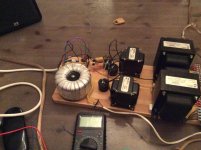
My main transf is 360 CT @ 0,3A toroid from Noratel with 6,0 V @ 5A filament heater. I am a bit high on the B+ so I had to drop a few volts.
I had some unexpected problems with my DMM as I was testdriving my amp. When the amp is on, it won’t measure correctly, the values are all over the place when I connect the testleads. I don’t know what causes this, electromagnetism or it can’t deal with high values but I have ordered a new Fluke 175. That should last me a lifetime hopefully.
I stumbled upon the Michael Abdellah circuit earlier and it looks very much like mine. Despite a few differences, I am thinking my amp should sound more or less like that one...
Hi
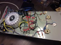
Thanks for tips on grounding the psu caps. I bundled them together and grounded the lot with one wire, dead silent with 90-92 dB speakers
I also had big problems with noise, crackling and the cathode current all over the place.
Turns out it had a strange cause. Had the G2 connected to anode on a screw terminal with wires coming from the tube socket, no gridstopper on G2 pin. Removed the wire and soldered in a 100R resistor between pin 3 and 4 to connect it for triode mode.
Now the amp plays like I have hoped it could, I dont know exactly what cured it but now it is fine
Maybe there was bad connection on the screw terminal, or the wires picked up something, I dont know. I checked every connection several times without any luck.
A grid stopper resistor has to keep any and all signals that would be picked up by wiring to be isolated from the grid.
The resistor is connected directly to the socket grid pin without any extra wire, just that of the resistor (and just a short portion of that resistor wire).
The resistor is connected directly to the socket grid pin without any extra wire, just that of the resistor (and just a short portion of that resistor wire).
Good evening
Both my OPTs have a rather high dcR, in the range of 400-500 Ohms. I loose 40-50 V of B+ each channel, that is ok tbh as it is a bit high after filtering (485 V)
I thought these OPTs should be around 150-200 ohms. They do not get especially warm either, a bit more than room temp.
Does this matter in any way other than the loss of B+? They work all right as far as I can tell.
Viking83,
Yes, transformer DCR of both the primary and DCR of the secondary do have consequences:
Take a 12.6 Watt amplifier that has a lossless transformer with a 4000 Ohm primary. Now, add 400 Ohms DCR to the primary, and you will only get 10.0 Watts.
Take an amplifier with no global negative feedback, and a plate resistance of 1000 Ohms, and a lossless transformer with a 4000 Ohm primary. The damping factor is 4. Now, add 400 Ohms of DCR to the 4000 Ohm transformer primary. The damping factor is 2.86.
No transformer is perfect. But I bet your amplifier sounds good.
And it did sound just like on the breadboard
I am a bit worried about DCR in the OPTs, theres not to much power for any to be wasted, but as far as I can tell it works ok. They dont get warm either.
Cant really understand what could have happened to them either, had some troubles with stability at first but I cant imagine it could have fried the OPTS??
Member
Joined 2009
Paid Member
Viking83,
6.0V should be OK, especially if the rating is with load (for example a 6.0V @5A rating, loaded by 3.5A).
But here are some other picky observations:
6.3 / 6.0 = +5%
6.0 / 6.3 = -5%
I see one KT88 data sheet that shows filament voltage range from
5.7 to 6.9 V (+ / - 10%)
Most tubes filaments voltage ranges are rated +/- 10% from nominal
Some tubes filament voltage range is rated for only +/- 5% from nominal
KT88 filament is rated 1.6A at 6.3V
2 KT88 3.2A
4 KT88 6.4A
Many people do not even think about it, but a single KT88 with no plate current and no screen current is already dissipating
10.08 Watts (6.3V @ 1.6A).
What is the Amp rating of your filament 6.0V winding, versus the load of all the tubes you will run on it?
Are you running the KT88s near their maximum rated cathode current (175mA)?
How about at the cathode current peaks (Plate + Screen at maximum signal before clipping)?
Maximum allowable cathode current is determined by the cathode size (area), cathode coating, and
how hot the cathode is (filament voltage). For a KT88, you can only control the filament voltage, the other factors are controlled by the manufacturer of the tube.
A really cold filament and cathode can not quite safely get to the maximum cathode current.
Power Mains outlet voltage varies, even at one location. So . . .
Your 6.0V will vary from day to night, and from day to day.
Your 6.0V will vary with the load (2 KT88, or 4 KT88, driver tube(s), etc.)
What other tubes will be run off the 6.0V filament winding?
What are the filament +/- % ratings of those tube types?
My power outlet voltage varies from 117V to 123V
123 / 117 = 5%
(120V + / - 2.5%)
I have many old transformers that are for 115V, or 117V, so the filament voltage is high when the power line is 120V.
I use a resistor in series with the filament to drop the somewhat high filament voltage to 6.3V.
I calculate the resistor to give 6.3V under filament load(s) when the power line is 120V (and then I measure it, just to be sure).
I am a little bit more careful than I need to be. I do make sure the range is 6.2V to 6.4V @ 120V (because the power line voltage range is large)
When I used to use 300B tubes, I made sure the filament was from 4.90 to 5.1V @ 120V power.
300B tube filaments are rated at + / - 5% (5V + / - 0.25 Volts).
One advantage is the series resistor limits the inrush current at start up, because the filament is cold and so starts out as a lower resistance, and the series resistor has more voltage across it at start up.
This is the simplest filament soft-start circuit.
But some designers do not want the filament and cathode to warm up slowly, because the B+ may be there first. It has not been a problem for my tubes, and I use fast starting B+, because I use solid state diodes, not tube rectifiers.
Last edited:
Thanks for replies!
Yeah, I had it rated for 6,0V @ 5 A, and as my amp draws 4,1A it is just a tad over 6V at running conditions. Ordered the PT from Noratel here in Norway, got it the way I wanted, built to order for the price of a Hammond transformer. Will be Noratels for me for the future.
Edit: I run my KT88s at approx 95-100 mA.
I really have no reference as to what a tube amp should sound, but as far as I can tell it sounds ok
Last edited:
- Status
- This old topic is closed. If you want to reopen this topic, contact a moderator using the "Report Post" button.
- Home
- Amplifiers
- Tubes / Valves
- E80CC/KT88 SE Triode/UL question