I suspect changing output transformer and valves will give little difference in sound.
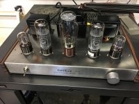
If he can fit a larger pair of output transformers on the chassis, it will make a decent difference. The ones the amp comes with look like they'd be good for 2-3W at 30Hz.
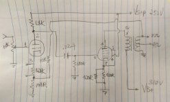
Looking up on my notes. I think this is the one tube front end schematic that you are looking for. A good first order mod will be to change (increase) the NFB and add a grid stopper resistor (it needs one). Also looks to me that the PCB designer originally wanted to put in a stuff option on a Cathode by-pass but did not put a jumper on the NFB point. I would change the NFB to the Cathode of the front end. The shipping version did not have the bypass cap.
I wouldn't change OPT. The copy I looked at is more than good enough for this chassis. I recalled it has decent performance down to 50Hz. If you must change something, IMHO, change the power transformer instead.
P.S. Looks like when I drawn the schematic, I forgot to add the EL34 Cathode by-pass Cap. I think it is 470uF.
Attachments
Last edited:
Folks I think you might be getting a little ahead of things here.
If the schematic I posted matches the Gemtune that Dave acquired then, the mods I already performed on a similar design are much simpler to implement.
I would suggest following that plan and trying to maximize the existing design before completely changing the front end and swapping out transformers.
For a couple hours of time and a few dollars in parts I ended up with an amp that was very satisfactory for my use.
Steve
A friend I have who is great at building speakers made himself his first tube amp in college when he was 19 without really knowing anything about tube amps. This schematic looks really close to what he built.Hi guys,
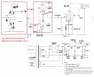
Gemtune wrote me back and sent a schematic. I've attached it. Let me know what you think.
This amp will have horrendous distortion, high output impedance, and potentially more noise than a properly designed amp would otherwise have.
This wouldn't be too bad as a guitar amp if you could get some more gain ahead of it.
YGWYPF
Audiowize,
Thank you for your reply. So far the amp hasn't produced much audible distortion at high volume levels on my 99db speakers. I'm happy with the amp so far, but I still haven't gone through all the checks that you and the others have outlined in this thread. I promise I will!
Can you provide some suggestions for a fun amp I can build? I've started looking at Pete Millett's webpage and am reading about some of his designs. I like the idea of buying a PCB for it. I'd prefer it make at least 20 watts per channel, use big tubes (like the KT88, 300B, or similar) for visual impact, and sound different than my existing solid state QSC amps.
Thanks again!
Dave
Attachments
Good. The schematic is the same one that I posted.
The basic design is capable of good performance.
It is a pentode SE it needs local or global feedback. The SRPP input stage has a lot of gain. It can approach the mu of the tube. Adding feedback will reduce the gain and cleanup the pentode output a lot.
I would add a grid stopper and a screen grid resistor. You could take the Screen Grid B+ from the B2 or B3 tap.
Before doing anything I would determine the operating point which can be done with only a multimeter.
Measure the resistance of the cathode resistor (do not rely on the values stated in the schematic). While the amp is idling measure the voltage drop across this resistor and then calculate the current thru it. Measure the plate and screen voltages referenced to the cathode. Compute the plate dissipation.
Let us know the results.
Allensoncanon: I used local feedback because I knew the quality of the transformers. In this case we don't and so global feedback may be the better approach. I don't know how to do that with and SRPP driver.
Steve
Good.
Allensoncanon: I used local feedback because I knew the quality of the transformers. In this case we don't and so global feedback may be the better approach. I don't know how to do that with and SRPP driver.
Steve
I would make a simple change and turn the SRPP into a Mu Follower than apply Global NFB. It make more sense for this chassis (IMHO).
- Status
- This old topic is closed. If you want to reopen this topic, contact a moderator using the "Report Post" button.
- Home
- Amplifiers
- Tubes / Valves
- Noob questions about Chinese tube amp