Hello. I found a shematic on the internet which looks promising in terms of functionality. I havent played arround with tube amps before. Only experinmenting pream stages.
I wanted to make a 50W tube Amp. Since i found this schematic and i wanted something powerfull this looked like a decent choice. I have also found a schematic for a 100W one but that would be a bit too much .
.
I want to make this happen. I dont know what output transformer i have to buy since there is nothing specified there.
If anyone knows that this will be 100% functional then please tell me and any kind of improvements are welcome. I want to use the amplifier as a general purpose amplifier. Music and stuff. Not for guitars.
Thanks.
I wanted to make a 50W tube Amp. Since i found this schematic and i wanted something powerfull this looked like a decent choice. I have also found a schematic for a 100W one but that would be a bit too much
. I want to make this happen. I dont know what output transformer i have to buy since there is nothing specified there.
If anyone knows that this will be 100% functional then please tell me and any kind of improvements are welcome. I want to use the amplifier as a general purpose amplifier. Music and stuff. Not for guitars.
Thanks.
Attachments
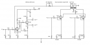
To get 50W from a pair of EL34 you need to run fixed bias. You can make 40W in AB using cathode bias.
I've drawn a schematic of the latter.
Here's the datasheet. https://frank.pocnet.net/sheets/129/e/EL34.pdf
I've drawn a schematic of the latter.
Here's the datasheet. https://frank.pocnet.net/sheets/129/e/EL34.pdf
Attachments
Even if this schematic uses fixed bias it will not get 50w output power with any output transformer.Hello. I found a shematic on the internet which looks promising in terms of functionality. <snip>
You will have to get B+ > 500V if you want 50w from a pair of el34 and that will be tough on the tubes.
I'd start at the other end ; find output transformers and then a suitable schematic for those transformers. The general advise is to build as simple as possible, few stages and no frills.
Cathode bias is generally less demanding although you will loose some power, something you probably don't notice, usually 25w is achieved useing EL34 and cathode bias. The lower power also makes choice of transformers easier and cheaper.
Wow that looks simple
Thanks.
You should be able to get full power with about 1V input.
Even if this schematic uses fixed bias it will not get 50w output power with any output transformer. You will have to get B+ > 500V if you want 50w from a pair of el34 and
that will be tough on the tubes.
I'd start at the other end ; find output transformers and then a suitable schematic for those transformers. The general advise is to build as simple as possible, few stages and no frills.
Cathode bias is generally less demanding although you will loose some power, something you probably don't notice, usually 25w is achieved useing EL34 and cathode bias. The lower power also makes choice of transformers easier and cheaper.
Looking at the datasheet its quite clear that i wont get 50W but 45 is good enough
I wont tweak the thing to absolute max ratings because i dont want my room to become a RTG scanning room and neither lit red by the plates lol.I have tested different EL34 PP amplifiers with fixed bias and with 6F12P triode pentode front end. With 4k output transformer and 460 V +Ub the available output power is from 55 W (UL) to 72 W (pentode).
Attached the schematic and some test results.
Attached the schematic and some test results.
Attachments
You should be able to get full power with about 1V input.
Great. Thanks. I sent you a direct message. Please check.
Hi Arto...Can I use your GU-50 power supply for this schematic?
Thanks!
Zekk
Basically you can, but that PS has regulated screen grid voltage too, that is not necessary required if +Ub is some 450 V and of course not with UL.
I have used this. The 68 V zener in this schematic can be replaced with a small electrolytic capacitor.
Then input voltage variations has the same effect on all voltages and less effect to idle current of output tubes.
Attachments
Last edited:
I have tested different EL34 PP amplifiers with fixed bias and with 6F12P triode pentode front end. With 4k output transformer and 460 V +Ub the available output power is from 55 W (UL) to 72 W (pentode).
Attached the schematic and some test results.
Hi Arto !
I've decided to build ur design but can I use ECF 82 instead of 6F12P ? If possible, what'll be the required changes?
Thanks!
If possible, what'll be the required changes?
Surely it is possible to use ECF82 instead of 6F12P. The main difference is the lower gm (=gain) of the pentode halve. Therefore the NFB-loop must be re-adjusted. Also the bias of both sections differ a lot from 6F12P. To put it briefly, the whole front end of the amplifier must re-designed for ECF82.
If you want to proceed with ECF82, the first thing is to find correct operating point for the pentode section. You can start with 47k plate resistor and the same cathode resistors I have used. Then search suitable value for the G2-resistor to get some 150 V at the anode. This can be later fine tuned with a distortion meter.
For the cathodyne, find suitable value for the cathode resistor to get 85...100 V at the cathode.
Other cathodyne resistors as in my schematic.
The feedback resistor (1k5 in the schematic) must be re-adjusted to get some 12...15 dB of NFB. Parallel capacitor should be tuned to get clean transient response of 10 kHz square wave. This depends a lot on the OPT you use.
Last edited:
- Status
- This old topic is closed. If you want to reopen this topic, contact a moderator using the "Report Post" button.
- Home
- Amplifiers
- Tubes / Valves
- Found schematic 50W EL34 AB. Needs help...