What an evil bunch 
jahsavage
Well done!
Leave it to play for a couple of days as the new parts will go through some break-in.
It is possible to run the tube a bit hotter. I doubt this will have a pronounced effect - the current op point is pretty good. There is also a chance the new parts just do no sound the same as the old, but there is no way to really know.
If you are still feeling unhappy, a different operating point at the same grid bias will mean higher plate voltage and more current.
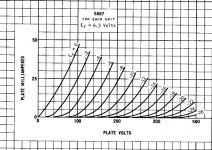
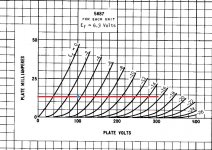
At approximately 110v, the current will be 20mA per tube. So, two diodes @10mA for the active load and a combined 25mA minimum for the PS ccs. Are such parts even available?
Part of the reason for my original suggestion was the availability of parts. Another was choosing a more symmetrical operating point, while keeping in mind that at low plate voltages and low currents the tube becomes increasingly non-linear.
jahsavage
Well done!
Leave it to play for a couple of days as the new parts will go through some break-in.
It is possible to run the tube a bit hotter. I doubt this will have a pronounced effect - the current op point is pretty good. There is also a chance the new parts just do no sound the same as the old, but there is no way to really know.
If you are still feeling unhappy, a different operating point at the same grid bias will mean higher plate voltage and more current.
At approximately 110v, the current will be 20mA per tube. So, two diodes @10mA for the active load and a combined 25mA minimum for the PS ccs. Are such parts even available?
Part of the reason for my original suggestion was the availability of parts. Another was choosing a more symmetrical operating point, while keeping in mind that at low plate voltages and low currents the tube becomes increasingly non-linear.
Attachments
All Finished
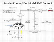
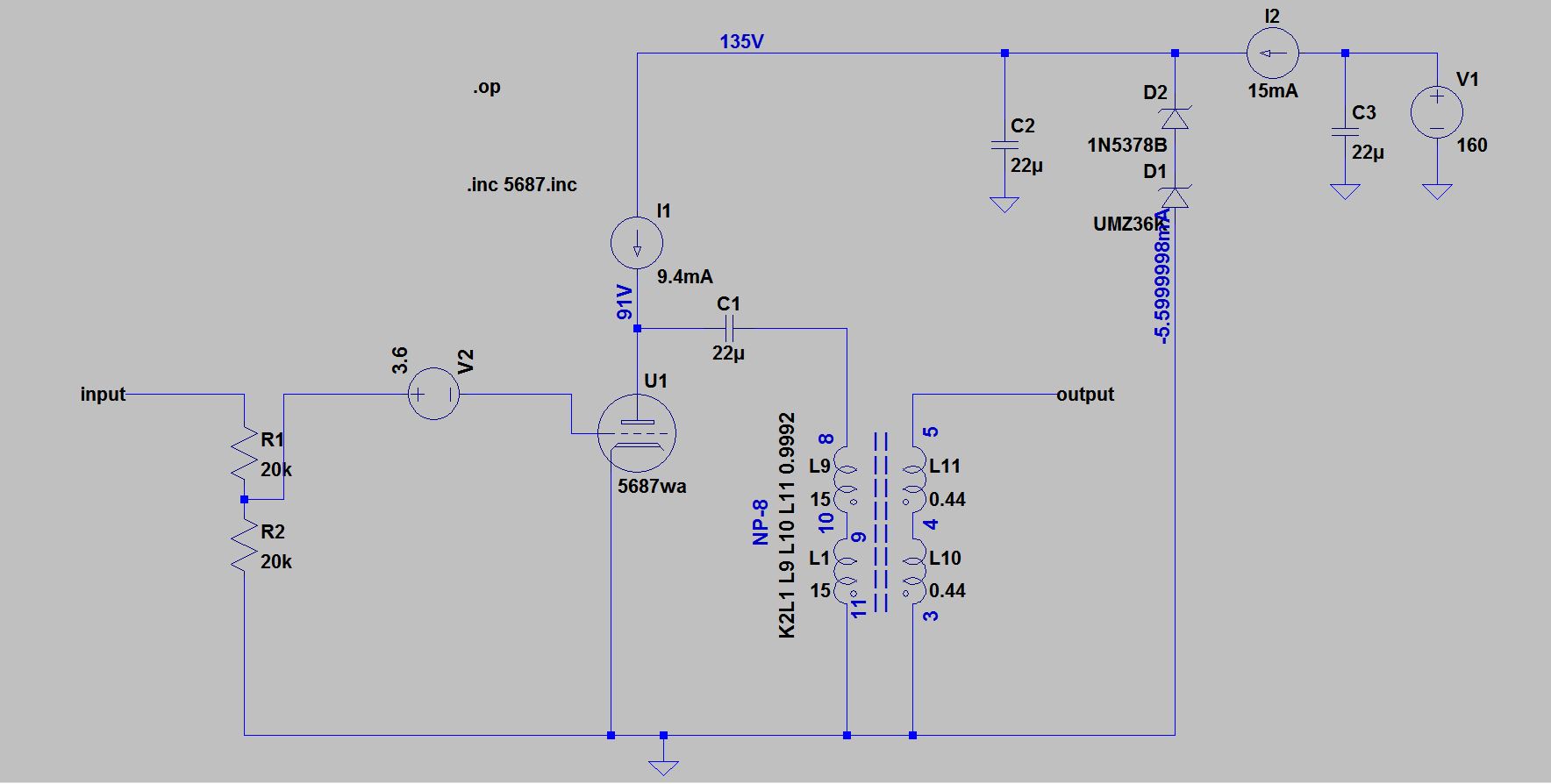
The initial current value I allocated to the zener branch was 2.2mA, but I found this was not sufficient to maintain the point voltage of 137v. For my next interaction I changed the rectifier CCDs to use three devices of 5.6mA, supplying 16.8 mA, 12.8mA would be Ia and 4mA for the zeners. This works great, the preamp is as good if not better than before. I do think 4mA maybe 1mA too much for Iz but with everything sounding so good I'm reluctant to make any more changes.
So the total repair cost was £44 for a selection of CCDs and lots of time and patience.
PS
The diagram shows the original component markings for the CCDs, I've used three in my repair to get what I believe is the correct current values. I've also attached my latest diagram including working voltages to help any others that may walk this path in the future.
I'd also like to offer a large raspberry to Zanden and their dealership for no help what so ever.
Attachments
Finally what's the bias -6.2V grid, 99/103V plate and 3,5mA?
The battery is in the grid.
The input is to the grids or cathode of the tube.. and the battery is in the grid or cathode circuit?
The battery is in the grid.
I think isn't correct.
What's the bias: 100V plate, -3,6V grid (as battery pic) & 13mA CCS?
The initial current value I allocated to the zener branch was 2.2mA, <snip>
What's the bias: 100V plate, -3,6V grid (as battery pic) & 13mA CCS?
I think isn't correct.
What do you mean?

Here I see -6.2V grid.
And i see "6.2v - return" indicating the heater is grounded. The pics of the pcb are in the thread for all to see and compare. The circuit drawn by myself as well. Besides, it is less alike a Picasso painting
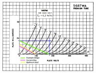
Also I wanna know if the optimal bias is 3.5mA, -3V grid & 60V?
This gets into the ugliest parts of the transfer characteristic. Who has ever suggested this to be optimal?
And i see "6.2v - return" indicating the heater is grounded. The pics of the pcb are in the thread for all to see and compare. The circuit drawn by myself as well. Besides, it is less alike a Picasso painting
This one?
What's the purpouse of C1?
Last edited:
This one?
What's the purpouse of C1?
Did you really ask that question??
That's not very Zen. You must argue to learn and become MasterAaah, The Master. With him i dare not argue
I made time ago a headphone amp based on a similar schematic, that's why I asked for information. Bias is 10mA each tube, 74V anode & -3.3V grid, Edcor OPT EDCOR GXSE5-15k_600 because my headphones are 300 ohms and I didn't used C1 because the OPT is air gapped to avoid saturate the core and makes the primary inductance of the transformer lower than those without an air gap.
Tamura TPB-203 isn't air gapped?
Did you really ask that question??
Tamura TPB-203 isn't air gapped?
- Status
- This old topic is closed. If you want to reopen this topic, contact a moderator using the "Report Post" button.
- Home
- Amplifiers
- Tubes / Valves
- Repairing Hi-End Preamplifier