Hi,
I´ve just received a lot of used 6p14p tubes bought from Fleabay.
When testing them to get an idea about the state of their emissions I´ve found that, for some tubes the plate current started to runway after about two minutes.
At about 15 seconds later and 70 mA I´ve aborted the test to save the output transformer.
For testing I´ve used a standard mono EL84 SE amplifier, that I use for casual listening at workshop.
For this trial I connected multimeter for reading the plate current.
Also verified that when the plate current began to runway, the bias at G1 started to move from -7v ...to -4V and aborted.
Just in case I have replaced the grid input capacitor, but no changes.
Can someone explain what is wrong with these tubes .
.
Regards
I´ve just received a lot of used 6p14p tubes bought from Fleabay.
When testing them to get an idea about the state of their emissions I´ve found that, for some tubes the plate current started to runway after about two minutes.
At about 15 seconds later and 70 mA I´ve aborted the test to save the output transformer.
For testing I´ve used a standard mono EL84 SE amplifier, that I use for casual listening at workshop.
For this trial I connected multimeter for reading the plate current.
Also verified that when the plate current began to runway, the bias at G1 started to move from -7v ...to -4V and aborted.
Just in case I have replaced the grid input capacitor, but no changes.
Can someone explain what is wrong with these tubes
.Regards
There's the problem.bought from Fleabay.
Unlucky buy probably.
I have bought a few items off ebay that failed soon after I bought them.
irf9240 failed after 10 minutes, RS replacement still going days later.
IRF4227 blew up even under moderate loading.
Leather belt that fell apart after a couple of weeks.
B9A pcb valve bases that were too tight and bent valve pins.
etc etc
I now just buy from reputable dealers.
The maximum rating of control grid resistor for the 6P14P is 1 meg Ohm for self bias.
And it is 300k Ohms for fixed bias (more if the plate dissipation is less than 75% of maximum rating).
What value of grid resistor does your amp have?
Do you use fixed grid bias?
Do you use cathode self bias?
What is the screen voltage in your amp?
What is the plate current and voltage?
Running a tube at or near its limits can cause thermal runaway.
How about a schematic of your amp, with voltages and currents?
Last edited:
I bought a batch of 100 6n14n. They are similar to 7189. Higher dissipation than EL84; 14Watts anode for 6n14n and 12Watts for EL84. Doesn't make your AC30 any louder, just last longer at high power.
Had zero failures so far and only got one quad left. More on order direct from Siberia. All brand new 1970s Old Stock in original box.
Had zero failures so far and only got one quad left. More on order direct from Siberia. All brand new 1970s Old Stock in original box.
Had a similar experience with a batch of 6n1p lately, running near max plate dissipation, current was all over the place drifting how ever and how often I tried to adjust bias pot, solution was to reduce grid leak resistor considerably, rock stable since then. Datasheet says 1 meg but they were all but happy with it, one third is O.K. now.
Also, when measuring current do not use ammeter, the long leads may cause oscillation, which can look like thermal runaway ... Better to solder small value resistor to anode pin and use voltmeter to derive current from voltage drop via ohm's law.
Also, when measuring current do not use ammeter, the long leads may cause oscillation, which can look like thermal runaway ... Better to solder small value resistor to anode pin and use voltmeter to derive current from voltage drop via ohm's law.
Hi,
Thanks to all for your comments.
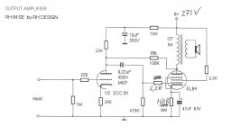
My amp is a RH84 modified to get a litle more power. I´ve atached the schematic with the some annotations.
At this moment I don´t remember the exact figures but the G2 Voltage was about 260V and the plate current range was from 40 to 46MA with the several tubes that were OK.
I bought these used tubes in an impulse buy and intended to mess with them in amplifier prototype trials or repair some tube radios from my personal small collection.
Tomorow I will do some tests running it with lower power and placing a capacitor across the connector where the multimeter probes are connected to decouple any eventual high frequency.
Regards.
Thanks to all for your comments.
My amp is a RH84 modified to get a litle more power. I´ve atached the schematic with the some annotations.
At this moment I don´t remember the exact figures but the G2 Voltage was about 260V and the plate current range was from 40 to 46MA with the several tubes that were OK.
I bought these used tubes in an impulse buy and intended to mess with them in amplifier prototype trials or repair some tube radios from my personal small collection.
Tomorow I will do some tests running it with lower power and placing a capacitor across the connector where the multimeter probes are connected to decouple any eventual high frequency.
Regards.
Attachments
Go to a smaller grid leak (220-270k) and go for a bigger cathode resistor (220R or so) and take what power you can get. Worst case regulate the screen voltage and make it adjustable.
With many of these "lightly used" or dubious bulk lot tubes from former Soviet countries, often you need to take special care to use them, unless buying late-production NOS that were handled and stored properly...
With many of these "lightly used" or dubious bulk lot tubes from former Soviet countries, often you need to take special care to use them, unless buying late-production NOS that were handled and stored properly...
They are probably gassy. Some may improve, most will not.
Yes to the gas issue. As I've posted before, a good number of them that I handled/sold were gassy when I got them and required "burn-in" to prevent issues with them in use. Most were fine after the burn-in.
I did not handle any used tubes - all mine were NOS.
On the gas issue:
The last batch of GU50 had 7 out of 10 which flashed over on the test bench at no more than 300 volts.
Now this is a 1000 volt tube ! Fortunately no damage done , current limiter did its job.
Running these tubes with just the heater on for a mere hour seems to have cured them, none have failed at 500 v so far.
Interestingly enough the date code of these tubes was from just prior to the turnover in the ussr.
All GU50s I had bought before - date codes 76, 79, 81, 88 did not have this problem !
Burn-in
Jim,
I have few 6P14P-ev and I may use them in a near future. Do you mind to tell us what's your burn-in process?
Thanks
Jim,
I have few 6P14P-ev and I may use them in a near future. Do you mind to tell us what's your burn-in process?
Thanks
Yes to the gas issue. As I've posted before, a good number of them that I handled/sold were gassy when I got them and required "burn-in" to prevent issues with them in use. Most were fine after the burn-in.
I did not handle any used tubes - all mine were NOS.
Today I changed the G1 escape resistor to 330K and connected a capacitor across the multimeter probes connector, but again the plate current after 2 minutes was excessive.
Then wired the filaments of all suspect tubes in parallel and let them heating for 3 hours without HV.
Tested the tubes again, but no changes!
Then wired the filaments of all suspect tubes in parallel and let them heating for 3 hours without HV.
Tested the tubes again, but no changes!
Even if you have good EL84 or 6P14P tubes, check the following:
How good is your coupling cap from the driver plate to the output tube grid? Even though you only have 270V B+, I would not use a 400V cap there, I would use a 600V or 630V cap. And I would not use a paper cap, etc.
You are using a 160 Ohm cathode resistor; probably causes a bit too much current for the EL84, and perhaps a bit too much plate dissipation, and also too much screen current.
So do some measurements:
You can measure plate plus screen current, just measure the voltage across the 160 Ohm resistor, and calculate: Cathode voltage/160 = plate + screen current). Then measure the voltage Across the screen resistor (voltage/2.2k Ohm = screen current).
Cathode current - screen current = Plate current
Plate voltage - cathode voltage = Plate to cathode voltage.
Multiply by plate current to get the plate dissipation.
And even though the EL84 specifies a large maximum grid resistor for self bias, that probably will not work when you are stressing the tube with lots of current. Use the 220k Ohm grid resistor that was suggested by another writer in this thread.
What is the cathode voltage? What is the screen current? Why is the control grid voltage when the cathode current starts to rise; if it starts increasing, you have a leaky tube. From that we can determine if a good EL84 will have stable current when it warms up; a poor tube will not.
Last edited:
- Status
- This old topic is closed. If you want to reopen this topic, contact a moderator using the "Report Post" button.
- Home
- Amplifiers
- Tubes / Valves
- 6P14P plate current runway